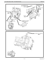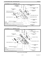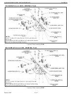
Procedure 9A - CPU / Power Supply Mounting Bracket Removal
1. Turn power off by disconnecting AC power to the system.
2. Remove rear cover. Refer to Procedure 2A.
3. Remove CPU assembly. Refer to Procedure 8A.
4. Remove power supply. Refer to Procedure 9A.
5. Disconnect slack spring.
6. Free any wiring harnesses required.
7. Remove (6) M5 socket head cap screws, SHCS and (6) M5 lockwashers.
Procedure 9B - CPU / Power Supply Mounting Bracket Replacement
1. Position CPU / power supply mounting bracket against actuator casting.
2. Install (6) M5 socket head cap screws, SHCS and (6) M5 lockwashers.
3. Reconnect
slack
spring.
4. Reinstall power supply. Refer to Procedure 9B.
5. Reinstall CPU assembly. Refer to Procedure 8B.
6. Reposition any wiring harnesses as required.
7. Reinstall rear cover. Refer to Procedure 2B.
8. Restore AC power to the system.
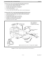
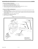
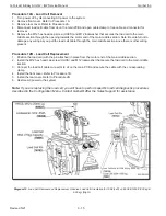
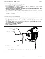
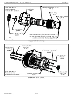
Diagram 9. CPU/Power Supply Mounting Bracket Removal and Replacement.
6x M5 Lockwasher,
High-Collar
(
65062
)
CPU/Power Supply
Mounting Bracket
(
76526
)
RUBBER
GROMMET, 3/8”
(
79255
)
Note: Numbers in
Parentheses are
Gorbel® Part Numbers
NYLOCK NUT M6
(
65090
)
6x SHCS M5 X 12
(
650020
)
4x SHCS M4 X 10
(
76304
)
4X M4
LOCKWASHER
(
65052
)
POWER SUPPLY BRACKET
(
76515
)
LOOP CLAMP
NOTE:
ADD SPOT OF LOCTITE TO THREADS OF P/N
65002
G-Force® & Easy Arm Q2 - iQ2 Service Manual
Gorbel Inc.
Revised 5/21
9 - 12


