background image

G-Force® & Easy Arm Q2 - iQ2 Service Manual

Gorbel Inc.

Revised 5/21

9 - 64

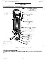
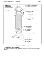
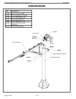
Procedure C-4. Standard Air Hose Assembly (G-FORCE.AIRHOSE.ASSEMBLY)

Diagram 4. Standard Air Hose Assembly

Note: The Extended Air Hose Assembly uses 2x as much Nylon Air Hose.

G-FORCE.AIRHOSE.ASSEMBLY

For replacement of entire Air Hose Assembly use part name: G-FORCE.AIRHOSE.ASSEMBLY.

G-FORCE.AIRHOSE.EXT.ASSEMBLY

For replacement of entire extended Air Hose Assembly use part name: G-FORCE.AIRHOSE.
EXT.ASSEMBLY.

2x Strain-Relief Clamp

(

65105

)

2x Adapter, DN8 (1/4 NPT)

(

74238

)

64x Nylon Air Hose, Coiled

(

74237

)

Hose Swivel, 90, DN8 (1/4 NPT)

(

74243

)

Note: Numbers in 
Parentheses are 
Gorbel® Part Numbers

Summary of Contents for G-Force iQ2 Series

Page 1: ...sy Arm Q2 and iQ2 Series All Models All Capacities Gorbel Customer Order No Serial No Service Manual Issued 5 2021 PLEASE NOTE This is the Service Manual for Gorbel s G Force and Easy Arm Q2 iQ2 units...

Page 2: ...G Force Easy Arm Q2 iQ2 Service Manual Gorbel Inc Revised 5 21 0 1 This page intentionally left blank...

Page 3: ...on I Functional Failure Table 6 2 LED Chart 6 6 Troubleshooting Section II System Fault Diagnostics Chart 6 7 Q2 iQ2 Fault Error Warning Code Corrective Actions 6 9 Chapter 7 Electrical Schematics 7 1...

Page 4: ...G Force Easy Arm Q2 iQ2 Service Manual Gorbel Inc Revised 5 21 0 3 This page intentionally left blank...

Page 5: ...with out first checking for proper limit switch action 7 Avoid impact between two hoists or between hoist and end stop 8 Do not tamper with or adjust any parts of the hoist unless specifically authori...

Page 6: ...ting Media 3 16 dia 19x7 Preformed Stainless Steel Wire Rope 1 4 dia 19x7 Preformed Stainless Steel Wire Rope Operating Temperature Range F C 41 122 5 50 Operating Humidity Range Non Condensing 35 90...

Page 7: ...oke ft m 8 2 4 Primary Voltage VAC Single Phase 220 10 Maximum Current Amps 6 Duty Cycle H5 H5 H4 H3 Available Tooling Power 24VDC 0 5A Lifting Media 3 16 dia 19x7 Preformed Stainless Steel Wire Rope...

Page 8: ...ting the control handle raise the wire rope assembly to the upper limit 4 Disconnect the coil cord assembly from both the actuator and the handle or swivel assembly Pack these components carefully to...

Page 9: ...ieving consistent positioning to 0 5 inches UPPER LIMIT Keep the hook at the desired position and select to set the upper limit LOWER LIMIT Keep the hook at the desired position and select to set the...

Page 10: ...to the main selection menu FSH Shortcut FAST ZERO FSH This menu provides a short cut to tare the Force Sensing Handle Clicking the Float Mode button will perform the tare process NOTE This menu will n...

Page 11: ...e tooling swings heavily If the total lifted weight e g tool and part is less than the maximum force limit Over Speed Detection is applied OVER FORCE OVER SPEED TURN ON SS CHECK Steady State Check mon...

Page 12: ...pacity plus 5 lbs for all other models Minimum Limit 25 of the rated capacity Note a This can be monitored in Run Mode if WT READ ON is selected in the settings Menu b A warning is triggered if the ta...

Page 13: ...setting for the slide and pendant handle run modes Read Only SET LIMIT SEC MIN Set the run mode Idle Time Exceeded timer by clicking the MENU pushbutton to increment the timer one second at a time Pr...

Page 14: ...the Access Point and accessing the Visual Interface via a VNC viewer XXX XXX XXX XXX RETURN TO MAIN MENU Return back to the main selection menu ADVANCED SETTINGS Overview These menu options are availa...

Page 15: ...op with WiFi connectivity or RJ45 port and Cat5 Ethernet cable VNC Viewer software tool installed on computer Q2 or iQ2 G Force Easy Arm 220VAC Power Supply to the G Force 4 Responsibilities Operator...

Page 16: ...re that USB drive has been removed before this step Figure 2 System Configurations Page Import 5 2 Updating New Software from V2 0 0 5 2 1 Copying current configuration to the USB Power on the G Force...

Page 17: ...ted During this process the CPU will reboot at least once LEDs will flash o There is no other visual feedback that the USB update is in progress When the handle reads G Force Ready to Lift it indicate...

Page 18: ...top left column for SW Version and verify that it matches the desired upgrade 6 References Refer to Appendices Appendix B AP VNC Viewer Install Instructions Appendix C AP Connection Quick Start Guide...

Page 19: ...This page is intentionally left blank G Force Easy Arm Q2 iQ2 Service Manual Gorbel Inc Revised 5 21 5 5...

Page 20: ...e refer to Trouble shooting Section II System Fault Diagnostic Chart in this chapter of the Service Manual D If there is something visually wrong such as a damaged wire rope damaged coil cord or somet...

Page 21: ...MODE Run Mode Overload Red WARNING LIFT OVERLOAD Overspeed No Light FLOAT MODE OVERSPEED Handle Idle Timeout Amber IDLE TIME EXCEEDED Handle Mode Green RUN MODE HANDLE Float Mode Blue RUN MODE FLOAT...

Page 22: ...e Replace PLC CPU 3 No Actuator LEDs AC power cable Damaged or defective power cable Repair or replace AC power cable Drive power cable Damaged or defective drive cable Replace drive cable DC power Da...

Page 23: ...CPU 5 Unit will not move up or down in Float Mode Feature not enabled Software not configured Unlock feature in visualization software Loadcell cable Loadcell cable to main PCB disconnected or damaged...

Page 24: ...ransducer Handle mother PCB Damaged defective handle mother board Replace slide or pendant handle mother board Handle operator present sensor Damaged operator present sensor falsely keep unit running...

Page 25: ...than 60 seconds Sliding Handle Operator present sensor Clean the sensor and remove any blockage Pendant Handle Either lever Look for interference with the levers 14 Air Leaking at Swivel Assembly O r...

Page 26: ...it Fault Error Warning Categories A Command Faults Sub Category Fault Examples 1 Unit Configuration Setting Mismatched configuration settings 2 Supplemental tools Problem saving configuration settings...

Page 27: ...kup or repair For example if the fault category is CAN Communication check all the cable wiring and connectors for loose connections If the fault category is Motor Regen and Junction Temperature user...

Page 28: ...modules than the maximum limit of 5 Reaction N A Cause Remedy a Check if PLC model CP 0482 has any add on modules b Check if PLC model CP 0482 has a DM 9324 add on module c Reboot the unit d Please c...

Page 29: ...span and height version value Reaction Lift program terminates processing to prevent running with an incorrect configuration setup Cause Remedy A critical configuration setting of the unit is corrupte...

Page 30: ...Lift program terminates processing to prevent running with an incorrect configuration setup Cause Remedy a Please review the configuration shown on the CONFIG I O page of the visualization to correct...

Page 31: ...operly configure its position Cause Remedy a Check for any mechanical binding that could engage both the upper and lower limit switches b Check if the limit switch cable is properly connected to the A...

Page 32: ...While running through Jog Handle Float or other custom motion a processing command has taken too long to execute Reaction Lift is shut down if the excessive delay is caused by any problem in the lift...

Page 33: ...n this error is gener ated S is for the latter feature that triggers the fault B ACOPOS Drive Faults Error ______ ERROR_ACOPOS_FAULT Description ACOPOS drive faults or warnings Reaction Lift is shut d...

Page 34: ...is greater than the acceptable range from the nor mal bias value for this unit The acceptable range of this parameter is empirically determined and selected for di erent models and capacities Reactio...

Page 35: ...ed and handle display warning on the OLED Cause Remedy a Check for any mechanical binding that could engage both the upper and lower limit switches b Check and correct if the limit switch cable is con...

Page 36: ...ning Error 11007 WARN_UO_BELOW_MIN_LIMIT Description This warning is triggered when User Programmable Overload attempts to tare a weight less than 25 of the rated capacity Reaction The tare weight is...

Page 37: ...essary and it can vary based on the actual usage Please examine the wire rope and replace if necessary After replacement activate Program Mode with the handle browse to SERVICE MENU and scroll to CLEA...

Page 38: ...ayed on the OLED screen Access to Program Mode is disabled Cause Remedy A fault specifically a CAN bus alarm can occur if the CAN controller board does not com municate with the PLC correctly is in a...

Page 39: ...s spare IO block are either disabled or outputs turned o Cause Remedy A fault specifically bus o exception can occur if the X67 spare IO block CAN control ler does not communicate with the PLC correct...

Page 40: ...Chapter 7 Electrical Schematics NOTE These two pages should be viewed as a single illustration of the system schematic G Force Easy Arm Q2 iQ2 Service Manual Gorbel Inc Revised 5 21 7 1...

Page 41: ...umbers represent the replacement part numbers for the individual wiring harnesses with connections where applicable NOTE Q2 CPU shown for this example G Force Easy Arm Q2 iQ2 Service Manual Gorbel Inc...

Page 42: ...This page is intentionally left blank G Force Easy Arm Q2 iQ2 Service Manual Gorbel Inc Revised 5 21 7 3...

Page 43: ...ACTUATOR PCB GEN 2 G Force Easy Arm Q2 iQ2 Service Manual Gorbel Inc Revised 5 21 7 4...

Page 44: ...e 11 and 21 on the Actuator DM module equal 1 and 2 on the HMI screen 12 and 22 on the DM module equal 3 and 4 on the HMI screen etc See illustrations below The PS module has the same numerical layout...

Page 45: ...This page is intentionally left blank G Force Easy Arm Q2 iQ2 Service Manual Gorbel Inc Revised 5 21 7 6...

Page 46: ...Diagram 9 Handle IO Detail Slide Model iQ2 Handle to external I O block wiring Slide and Force Sensing Handles G Force Easy Arm Q2 iQ2 Service Manual Gorbel Inc Revised 5 21 7 7...

Page 47: ...Diagram 10 Handle IO Detail Pendant Model iQ2 Handle to external I O block wiring Pendant Handle G Force Easy Arm Q2 iQ2 Service Manual Gorbel Inc Revised 5 21 7 8...

Page 48: ...Q2 Handle Input Output Wiring Harness Schematic Gorbel P Ns Length 80187 1M Long 80188 2M Long 80189 3M Long See illustration below G Force Easy Arm Q2 iQ2 Service Manual Gorbel Inc Revised 5 21 7 9...

Page 49: ...Diagram 1 Upper Limit Switch The bottom allen head screw adjusts the upper limit Use a 5mm allen wrench to perform the adjustment Turning the screw clockwise raises the stop point of the wire rope Cou...

Page 50: ...ition as shown in diagram 5 below If the drum does not reach this position when it stops turn the upper allen head screw 1 2 turn counterclockwise with a 5 mm allen wrench Jog the wire rope up one ful...

Page 51: ...nostics View the active Ana log Signal under the Handle component of the page 2 Do not move the slide portion of the handle at all during this process 3 To decrease the number on the display turn the...

Page 52: ...the other end 3 Using a 10mm open end wrench loosen the nut closest to the eye inside nut on eyebolt diagram 5 Diagram 5 4 If chatter or erratic operation of hoist while traveling down is encountered...

Page 53: ...on an Easy Arm diagram 6 should be rotated 90 degrees clockwise to give you the correct orientation of the actuator The end result of the adjustment should be the same as it is for a G Force Diagram 6...

Page 54: ...s All Gorbel part numbers are shown in parentheses and bold print Index Actuator 9 2 Sliding Handle 9 31 Pendant Handle 9 40 Force Sensing Handle 9 53 Coil Cords 9 61 G360 9 65 Easy Arm Components 9 7...

Page 55: ...5104 1320 35105 75kg 35107 150kg 35109 300kg 35110 600kg 35111 Plug 79274 2x Gorbel Label 76550 3x G Force Label 83178 Model Label See Table Below for P N Note Numbers in Parentheses are Gorbel Part N...

Page 56: ...de front cover over ACOPOS assembly and align four holes with brackets attached to the actuator casting 2 Install 4 M5 button head cap screws BHCS 3 Restore AC power to the system Diagram 1 Front Cove...

Page 57: ...4 EXTERNAL TOOTH 65056 2x HEX NUT M4 ZNPL 65057 STRAIN RELIEF CLAMP 65105 FLAT WASHER M4 ZNPL 65081 NYLOCK NUT M4 ZNPL 65096 2x PANDUIT LATCHING WIRE CLIP 9 6mm 76517 13x PANDUIT LATCHING WIRE CLIP 6...

Page 58: ...2B Rear Cover Replacement 1 Carefully slide rear cover over ACOPOS assembly and align four holes with brackets attached to the actuator casting 2 Install 4 M5 button head cap screws BHCS 3 Restore AC...

Page 59: ...hield on the actuator main PCB 2 Install 4 M3 socket head cap screw SHCS and M3 lockwashers 3 Tighten all hardware carefully to avoid damaging the electrical shield 4 Install the front cover Refer to...

Page 60: ...B Main PCB Replacement 1 Install 5 M3 socket head cap screws SHCS and M3 lockwashers 2 Connect cable assemblies to J1 through J14 on the main PCB Check the cable numbers for cable assemblies that conn...

Page 61: ...derside of CPU power supply mounting bracket 2 Install 4 M4 button head cap screws BHCS and M4 lockwashers 3 Connect cable assembly 4 Install rear cover Refer to Procedure 2B 5 Restore AC power to the...

Page 62: ...to PCB ACOPOS support bracket with the 2 M6 Nylock nuts 2 Position PCB ACOPOS support bracket with ACOPOS servo drive attached onto hinge bracket and install 2 M6 Nylock nuts 3 Swing ACOPOS assembly i...

Page 63: ...tabs locking CPU onto DIN rail and gently tug CPU to ensure proper connection to bracket 3 Connect all cable assemblies to CPU and any I O wiring if necessary Check the cable numbers for cable as semb...

Page 64: ...O GAP BETWEEN THE I O SLICE 78516 AND THE CPU 78510 If there is a gap start over at step 1 6 Latch the Backplane 78515 onto the Din Rail by lowering the Orange Lever Tab until it clicks into the locke...

Page 65: ...s SHCS and 6 M5 lockwashers 3 Reconnect slack spring 4 Reinstall power supply Refer to Procedure 9B 5 Reinstall CPU assembly Refer to Procedure 8B 6 Reposition any wiring harnesses as required 7 Reins...

Page 66: ...ligned 2 Position slack spring bracket on left side of motor set and secure motor set with 4 M6 socket head cap screws SHCS and M6 lockwashers Note Do not tighten hardware completely until all 4 screw...

Page 67: ...Install the ACOPOS support bracket with electrical shield main PCB and ACOPOS servo drive Connect all cable assemblies to the main PCB and ACOPOS drive Refer to Procedure 5B 3 Install the front cover...

Page 68: ...e load cell with the pin attached in place from the motor end of the main middle section 2 Install the M12 hex head cap screw HHCS and M12 lockwasher that secure the load cell to the main middle secti...

Page 69: ...e Brace 76761 2x M8 Nylock Nut 65103 330 lb 150 kg Model Only Load Plate Brace Note Numbers in Parentheses are Gorbel Part Numbers Load Plate Brace 76522 2x M8 Nylock Nut M8 ZNPL 65103 660 lb 330 kg M...
Page 70: ...lacement 1 Position the drum cover band inside the drum cover and slide the assembly over the drum pulley 2 Install the 2 M6 socket head cap screws SHCS and 2 M6 lockwashers for the drum cover band in...

Page 71: ...shers from the drum gate and slide the drum gate off the load plate Procedure 14B Drum Gate Replacement 1 Slide the drum gate into position on the load plate and install the 2 M6 socket head cap screw...

Page 72: ...5 x 12mm Lg 65000 Apply Blue Loctite Note Numbers in Parentheses are Gorbel Part Numbers Diagram 14C 660 lb 300 kg Clearance Drum Gate Removal and Replacement Drum Gate Clearance 76510 2x Lockwasher M...

Page 73: ...te BHCS 65075 should provide slide fit for limit switch assembly do not fully thread into load plate Diagram 14E 330 lb 150 kg BHCS M6 x 16mm Lg 65075 Nylock Nut M6 65090 Ball Bearing 6908 Double Seal...

Page 74: ...6705 onto drum so the wire rope slot matches up to the wire rope anchor point on the drum pulley 79155 Diagram 14G 660 lb 300 kg Note Numbers in Parentheses are Gorbel Part Numbers 4x SHCS M8 x 25mm L...

Page 75: ...ed 76565 Load Plate 76503 2x Ball Bearing 6824 2RS 74011 4x Lockwasher M6 ZNPL 03370 5x SHCS M6 x 20mm Lg 00186 Note Numbers in Parentheses are Gorbel Part Numbers Note Numbers in Parentheses are Gorb...

Page 76: ...ssembly on the load plate by locating it on the inside M6 button head cap screw BHCS The lower projection of the slide must be engaged in the recess in the threaded gate 2 Install the M6 button head c...

Page 77: ...00195 4x M8 SHCS 83236 2x 3 8 Lockwasher 01355 4x 3 8 Hexnut 02158 U Bolt 83265 Note Coil cord and associated components not shown for clarity Note Numbers in Parentheses are Gorbel Part Numbers Note...

Page 78: ...Spacer 83259 M6 SHCS 2x 17mm Snap Ring 2001 12 Pulley Pin 83258 2x Pulley Side Plate 83254 2x Pulley Side Plate Spacer 83257 4x PHMS 4 40 x 1 4 83266 2x Pulley Side Guard 83256 Coil Cord Footer 83250...

Page 79: ...sembly 76591 NOTES a C H 1 is either of 2 holes o center C H 2 is center hole with slot to edge b Part numbers 65020 and 00206 are not included with assembly and must be ordered separately if required...

Page 80: ...ey Assembly 76597 NOTES a C H 1 is either of 2 holes o center C H 2 is center hole with slot to edge b Part numbers 65020 and 00206 are not included with assembly and must be ordered separately if req...

Page 81: ...ey Assembly 76592 NOTES a C H 1 is either of 2 holes o center C H 2 is center hole with slot to edge b Part numbers 65020 and 00206 are not included with assembly and must be ordered separately if req...

Page 82: ...apter Trolley Complete Trolley Assembly 76593 NOTES a C H 1 is either of 2 holes o center C H 2 is center hole with slot to edge b Part numbers 65020 and 00206 are not included with assembly and must...

Page 83: ...G Force Easy Arm Q2 iQ2 Service Manual Gorbel Inc Revised 5 21 9 30 This page is intentionally left blank...

Page 84: ...assembly with the PCBs facing upward to avoid damaging them Procedure S 1B Swivel Sub Assembly Replacement 1 Slide the swivel assembly onto the top of the handle shaft ensure PCB tabs align to the sl...

Page 85: ...ctrical connector locat ed below the remote mount cap 2 Position the handle assembly into the remote mount bracket if applicable and install M16 hex head cap screw HHCS flatwasher and lockwasher onto...

Page 86: ...components can be removed or replaced if necessary use the exploded view drawings as a reference 2 Once all the internal components have been positioned properly slide the handle bumper in place on th...

Page 87: ...ESD Ground Wire Not Shown E Stop Pushbutton Assembly 78804 E Stop Pushbutton Assembly 78804 Emergency Stop Label 74225 Light Pipe 74216 3x PHMS M2x0 4 6 SEMS Split Lock 65073 O Ring 10mm ID 1mm Thick...

Page 88: ...e Grip and Shaft Assembly Reassembly 1 Install the grip assembly up from the bottom portion of the handle shaft and position the grip assembly so that the ball bearings can be installed into the groov...

Page 89: ...Bracket Assembly with Hardware P N 74350 BHCS M6 x 16mm Lg 65075 Remote Mounted Slide Handle G FORCE RM SLIDE HANDLE Lockwasher M6 ZNPL 03370 Bracket Remote Mount 74270 Flatwasher M16 ZNPL 01310 Lock...

Page 90: ...Handle G FORCE SLIDE HANDLE Latch Hook Assembly 74199 Bracket In Line Slide Handle 74273 Lockwasher M16 ZNPL 00212 HHCS M16x2 0 35 Gr 8 8 ZNPL 65066 Note Numbers in Parentheses are Gorbel Part Number...

Page 91: ...Lever Guard 40mm Wide 8 65075 BHCS M6 x 16mm Lg 9 65076 BHCS M6 x 10mm Lg 10 65100 HHCS M6x1 0 20 ZNPL 11 65060 Flatwasher M6 ZNPL 12 03370 Lockwasher M6 ZNPL 13 01764 Hexnut M6 ZNPL 8 1 10 11 12 2 5...

Page 92: ...P N Description 1 74272 Bracket Block Mount 2 74330 Electric Switch Block Single 3 Ref BOM Switch Body w Roller Plunger 4 65027 SHCS M4 x 20mm Lg 5 65052 Lockwasher M4 ZNPL 6 88604 Left Angled Lever...

Page 93: ...2 M6 button head cap screws BHCS and M6 lockwashers 4 Remove the 2 side guards o each side of the pendant handle Procedure P 1B Top Side Guard Replacement 1 Position the top guard on the top portion o...

Page 94: ...lever shaft 3 Remove both levers from the pendant handle Procedure P 2B Lever Replacement 1 Position both levers on the pendant handle 2 Install the lever shaft 3 Install the side guard Refer to Proce...

Page 95: ...ews BHCS and M6 lockwashers Procedure P 3B Handle Base Bracket Replacement 1 Install 2 M6 button head cap screws BHCS and M6 lockwashers 2 Reattach the handle base bracket to clamp collar or tooling i...

Page 96: ...d rear cover gasket Procedure P 4B Rear Cover Replacement 1 Position rear cover gasket and rear cover on pendant handle assembly 2 Install the 6 M3 button head cap screws BHCS and M3 lockwashers that...

Page 97: ...achined holes in the pendant handle body then slide the pendant mother board into the daughter board 2 Install the 2 M3 button head cap screws BHCS and M3 starwashers to secure the pendant mother boar...

Page 98: ...ger Assembly Replacement 1 Install the plunger tips into the plunger assemblies 2 Install the plunger springs into the pendant handle housing 3 Install both plunger assemblies into the pendant handle...

Page 99: ...E stop assembly The switch part is disconnected from the inside first The pushbutton is then held in place by a nut that needs to be removed from the inside Procedure P 7B E Stop Assembly and Pushbutt...

Page 100: ...er side of the pendant handle housing either sepa rately or together b If using a single both of the switch valve block s then be sure to use either the Electric Pneumatic Mounting Plate Left Right 74...

Page 101: ...ZNPL 03370 7x BHCS M6 x 10mm Lg 65076 Side Guard 74313 Pneumatic Mounting Plate Left Right 74317 Top Guard 74335 9x Lockwasher M6 ZNPL 03370 Flatwasher M6 ZNPL 65060 Lever Shaft 105 74315 Side Guard V...

Page 102: ...M6 ZNPL 03370 4x BHCS M6 x 10mm Lg 65076 Pneumatic Mounting Plate Left Right 74318 Top Guard 74335 9x Lockwasher M6 ZNPL 03370 Flatwasher M6 ZNPL 65060 Lever Shaft 105 74315 Side Guard Valve Option 7...

Page 103: ...75 9x Lockwasher M6 ZNPL 03370 7x BHCS M6 x 10mm Lg 65076 Side Guard 74313 Pneumatic Mounting Plate Left Right 74317 Top Guard 74335 10x Lockwasher M6 ZNPL 03370 2x Flatwasher M6 ZNPL 65060 Lever Shaf...

Page 104: ...5076 Pneumatic Mounting Plate Both 74318 Top Guard 74335 10x Lockwasher M6 ZNPL 03370 2x Flatwasher M6 ZNPL 65060 Lever Shaft 105 74316 Single Electric Switch Block Assembly 74332 Right Angled Lever 8...

Page 105: ...G Force Easy Arm Q2 iQ2 Service Manual Gorbel Inc Revised 5 21 9 52 This page is intentionally left blank...

Page 106: ...o the handle shaft Note the orientation of the internal electrical connector located below the remote mount cap Procedure F 1B Remote Mount Cap Sub Assembly Replacement 1 Slide the remote mount cap on...

Page 107: ...ocedure F 2B Housing Sub Assembly Reassembly 1 All the sub assembly internal components can be removed or replaced using the exploded view drawings as reference 2 Once all the internal components have...

Page 108: ...achined 74197 Handle Plug M20 Thread 74217 ESD Ground Wire Not Shown E Stop Pushbutton Assembly 78804 Emergency Stop Label 74225 Light Pipe 74216 3x PHMS M2x0 4 6 SEMS Split Lock 65073 O Ring 10mm ID...

Page 109: ...ndles GRIP SHAFT 74146 24 SHORT 74144 24 SHORT 74145 36 LONG 74143 36 LONG 65077 INLINE STD QUANTITY INLINE AIR QUANTITY REMOTE QUANTITY 74206 1 1 74224 1 74221A 1 1 74233 1 74235 1 1 65083 1 74236 1...

Page 110: ...QUANTITY INLINE 1320 AIR QUANTITY 83255 1 1 83261 1 1 65086 1 1 83259 2 2 2001 12 2 2 83258 1 1 65018 4 4 65052 4 4 83250 1 1 83254 2 2 83257 2 2 83264 6 6 83263 2 2 03370 2 2 01764 2 2 83256 2 2 832...

Page 111: ...G Force Easy Arm Q2 iQ2 Service Manual Gorbel Inc Revised 5 21 9 58 Remote Force Sensing Hub SEE CHART 1...

Page 112: ...G Force Easy Arm Q2 iQ2 Service Manual Gorbel Inc Revised 5 21 9 59 FSH HUB Options...

Page 113: ...G Force Easy Arm Q2 iQ2 Service Manual Gorbel Inc Revised 5 21 9 60 This page is intentionally left blank...

Page 114: ...370 Standard Cable Assembly 78614 Hex Jam Nut M12 X 1 75 ZNPL 65064 2X BHCS M4 X 0 7 X 16 LG 65068 2X Strain Relief Clamp 74232 Plug Air DN8 1 4 NPT 74241 Coil Cord Footer 74205 Clevis Bolt 74222 Coil...

Page 115: ...BLY Coil Cord Bracket not included 165 lb 76757 330 lb 660 lb 76708 Note Numbers in Parentheses are Gorbel Part Numbers Wear Ring Machined 76766 BHCS M6 x 12mm Lg 65112 2x Lockwasher M6 ZNPL 03370 2x...

Page 116: ...2 Service Manual Gorbel Inc Revised 5 21 9 63 Procedure C 3 Pendant Cord Diagram C 3 Pendant Cable Electrical Portion Only G FORCE PENDANT CABLE For replacement of entire Cable Assembly use part name...

Page 117: ...Nylon Air Hose G FORCE AIRHOSE ASSEMBLY For replacement of entire Air Hose Assembly use part name G FORCE AIRHOSE ASSEMBLY G FORCE AIRHOSE EXT ASSEMBLY For replacement of entire extended Air Hose Asse...

Page 118: ...aft 6 Remove 3 M3 socket head cap screws SHCS and M3 lockwashers from the collector shaft and slide the collector shaft out of the cover Procedure G 1B G360 Reassembly Procedure 1 Slide the collector...

Page 119: ...G Force Easy Arm Q2 iQ2 Service Manual Gorbel Inc Revised 5 21 9 66 Diagram G 1a G360 with Air Assembly and Disassembly...

Page 120: ...G Force Easy Arm Q2 iQ2 Service Manual Gorbel Inc Revised 5 21 9 67 Diagram G 1b G360 Assembly and Disassembly...

Page 121: ...G Force Easy Arm Q2 iQ2 Service Manual Gorbel Inc Revised 5 21 9 68 This page is intentionally left blank...

Page 122: ...sembly Procedure 1 Press the bearing into the swivel casting if it was replaced 2 Install the primary slip ring PCB into the swivel casting by installing the input connector nut 3 M2 Phillips head mac...

Page 123: ...pended Pendant Swivel Assembly 74292 Clevis Pin 1 2 Dia 1 1 2 Lg ZNPL 74293 Cotter Pin Snap Ring Internal 47mm Basic 65086 Ball Bearing 6005 NSE 74221 Snap Ring External 25mm HD 65085 Suspended Pendan...

Page 124: ...nal 83203 Ball Bearing 6204 83202 Idler Carrier 165 330 83127 Ball Bearing 6204 83202 Pivot Pin 165 330 83111 Idler Pulley 165 330 83128 Ball Bearing 6301 83205 Retaining Ring 37MM Internal 83206 G Fo...

Page 125: ...28 Pulley Assembly Retaining Ring 37MM Internal 83206 G Force Easy Arm Q2 iQ2 Service Manual Gorbel Inc Revised 5 21 9 72 Pulley Block Assembly Pulley Assembly Nylock Nut M4 ZNPL 65096 Pulley Block Sp...

Page 126: ...5 83131 Follower Band 330 83132 Follower Axle 83133 Spacer 75336 Wheel Duracomp 0501 16 Retaining Ring External 17MM 2001 12 G Force Easy Arm Q2 iQ2 Service Manual Gorbel Inc Revised 5 21 9 73 Followe...

Page 127: ...Force Easy Arm Q2 iQ2 Service Manual Gorbel Inc Revised 5 21 9 74 Bumper Assembly Bumper Plate 165 83096 Bumper Plate 330 6 8 83097 Bumper Plate 330 10 14 83098 Bumper M6 83225 FHCS M10X25MM LONG 8322...

Page 128: ...p 83200 83134 Arm Assembly 00194 08249 83235 Follower Band Assembly Mast Weldment 83236 65103 P N Description 83200 Bearing Locknut 5N08 83134 Friction Break Ring 165 330 83236 SHCS M8x300MM Long 6510...

Page 129: ...embly Pulley Block Assembly Secondary Arm Assembly 65034 65070 83214 83207 83202 83208 83213 83212 P N Description 65034 SHCS M6x50MM Long 65070 Nylock Nut M5 ZNPL 83214 Nylock Nut M10 83213 Shoulder...

Page 130: ...Plate 165 10 14 Span 83090 Side Plate 330 10 14 Span 83091 Side Plate 330 6 8 Span 83109 M12 Bushing 83108 M10 Bushing 83214 Nylock Nut M10 83149A Side Plate Spacer 3 LG 83149B Side Plate Spacer 6 LG...

Page 131: ...G Force Easy Arm Q2 iQ2 Service Manual Gorbel Inc Revised 5 21 9 78 Head Assembly 2 Bumper Assembly 00258 83219 00259 83220 83149A 83149B NOTE Refer to previous page for part numbers...

Page 132: ...nual Gorbel Inc Revised 5 21 9 79 Secondary Arm Assembly Secondary Arm Weldment Retaining Ring 35 MM External 83211 Friction Brake Block 165 330 83135 Ball Bearing 6206 83209 Mast Bearing 4 83210 SHSS...

Page 133: ...orbel Inc Revised 5 21 9 80 Primary Arm Assembly Head Assembly Nylock Nut M12 ZNPL 83228 Wire Rope Guard 3in 83151 Wire Rope Guard 6in 83152 Primary Tube Assembly HHCS M12x110MM Long 83227 HHCS M12X12...

Page 134: ...G Force Easy Arm Q2 iQ2 Service Manual Gorbel Inc Revised 5 21 9 81 Primary Tube Assembly Primary Arm Weldment CAM 83114 SHCS M8x25MM Long 00194...

Page 135: ...G Force Easy Arm Q2 iQ2 Service Manual Gorbel Inc Revised 5 21 9 82 Easy Arm 660 Parts will be published in a future edition...

Page 136: ...G Force Easy Arm Q2 iQ2 Service Manual Gorbel Inc Revised 5 21 9 83 This page is intentionally left blank...

Page 137: ...flat and Phillips smaller precision type Long Nose Pliers 8 inch is typical Gorbel Part Number Spare Parts Kit Level 1 G Force SpareParts L1 Kit Basic Kit Wire Rope Coil Cord or Pendant Cable Level 2...

Page 138: ...93 Phone 800 821 0086 Fax 800 828 1808 Distributed by Ergonomic Partners Sales ErgonomicPartners com www ErgonomicPartners com Tel 314 884 8884 2021 Gorbel Inc All Rights Reserved G Force Easy Arm Q2...

Reviews: