


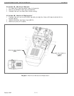


Procedure 4A - Main PCB Removal
1. Turn
o
ff
power by disconnecting AC power to the system.
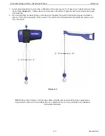
2. Remove front cover. Refer to Procedure 1A.
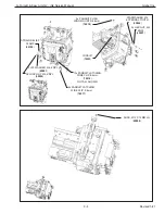
3. Remove electrical shield. Refer to Procedure 3A.
4. Unplug cable assemblies from J1 through J20 on main PCB. Note the cable numbers for cable assemblies that
connect to J4, J6, J13 and J15.
5. Remove (5) M3 socket head cap screws (SHCS) and M3 lockwashers.
Note:
Use caution when handling the main PCB; to avoid damage handle only by edges of board.
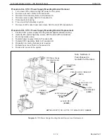
Procedure 4B - Main PCB Replacement
1. Install (5) M3 socket head cap screws (SHCS) and M3 lockwashers.
2. Connect cable assemblies to J1 through J14 on the main PCB. Check the cable numbers for cable assemblies
that connect to J4, J6, J13 and J15.
3. Install the electrical shield. Refer to Procedure 3B.
4. Install the front cover. Refer to Procedure 1B.
5. Restore AC power to the system.
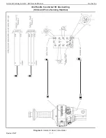
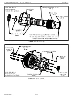
Diagram 4.
Main PCB Removal and Replacement
Note: Numbers in
Parentheses are
Gorbel® Part Numbers
Actuator Main PCB
(
80101
)
2x Lockwasher, M3, ZNPL
(
65051
)
2x SHCS, M3 x 12mm Lg
(
65012
)
Hex Standoff
(
01007
)
Metal Loop Strap, 1/2” ID
(
76525
)
Nylock Nut, M5, ZNPL
(
65070
)
G-Force® & Easy Arm Q2 - iQ2 Service Manual
Gorbel Inc.
Revised 5/21
9 - 7


