


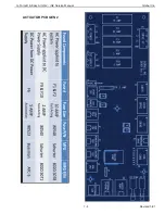


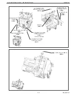


iQ2 Actuator CPU Input/Output Block
Note:
The numbering sequence for the PS and DM modules is as follows as they apply to the
Acutator I/O Con
fi
gurators on the HMI screens. For example, 11 and 21 on the Actuator DM module
equal 1 and 2 on the HMI screen. 12 and 22 on the DM module equal 3 and 4 on the HMI screen,
etc. See illustrations below. The PS module has the same numerical layout as the DM module.
DM
Module #
HMI
Screen #
11
1
INPUTS
21
2
12
3
22
4
13
5
23
6
14
7
24
8
15
1
OUTPUTS
25
2
16
3
26
4
G-Force® & Easy Arm Q2 - iQ2 Service Manual
Gorbel Inc.
Revised 5/21
7 - 5


