


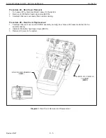


Procedure 10A - Motor Set Removal
1. Turn power o
ff
by disconnecting AC power to the system.
2. Remove rear cover. Refer to Procedure 2A.
3. Remove resolver and motor power cables from motor set.
4. Remove (4) M6 socket head cap screws (SHCS) and M6 lockwashers from motor set.
5. Carefully pry/wiggle motor set away from gearbox assembly.
Procedure 10B. Motor Set Replacement
1. Align key on motor set shaft with gearbox assembly and push motor set into gearbox assembly with mounting
holes properly aligned.
2. Position slack spring bracket on left side of motor set and secure motor set with (4) M6 socket head cap screws
(SHCS) and M6 lockwashers. Note: Do not tighten hardware completely until all (4) screws have been installed
and are hand tight.
3. Connect resolver and motor power cables to motor set.
4. Reinstall rear cover. Refer to Procedure 2B.
5. Restore AC power to the system.
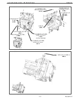
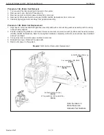
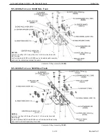
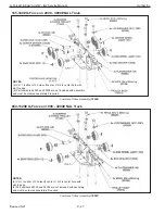
Diagram 10. Motor Set Removal & Replacement
36 Frame Motor (165 lb.)
(
78532
)
37 Frame Motor (330 and 660 lb.)
(
78533)
Note: Numbers in
Parentheses are
Gorbel® Part Numbers
Slack Spring Bracket
(
79239
)
4x Lockwasher, M6, ZNPL
(
00370
)
4x SHCS, M6 x 25mm Lg
(
65028
)
G-Force® & Easy Arm Q2 - iQ2 Service Manual
Gorbel Inc.
Revised 5/21
9 - 13


