ENGLISH
Read the instructions carefully before using the product and store
them for future use
GENERAL SAFETY REGULATIONS
If correctly installed and used, the
FALCON M
automated system will
ensure a high degree of safety. Some simple rules on behaviour
can prevent accidental trouble:
- Do not stand near the automatic system, and do not allow children,
persons or things to do so, especially when it is operating.
- Keep radio-controls, or any other pulse generators that could involuntarily
activate the automated system, well away from children.
- Do not allow children to play with the automated system.
- Do not willingly obstruct gate movement.
- Prevent any branches or shrubs from interfering with gate movement.
- Keep the indicator-lights efficient and easy to see.
- Do not attempt to activate the gate by hand unless you have released it.
- In the event of malfunctions, release the gate to allow access and wait
for qualified technical personnel to do the necessary work.
- When you have set manual operation mode, cut power to the system
before restoring normal operation.
- Do not in any way modify the components of the automated system.
- Do not attempt any kind of repair or direct action whatever and contact
qualified personnel only.
- At least every six months: arrange a check by qualified personnel of the
automatic system, safety devices and earth connection.
DESCRIPTION
The
FALCON M
automated system is ideal for controlling vehicle access
areas in residential environments.
FALCON M
for sliding gates is an electro-mechanical operator which tran-
smits motion to the leaf via a rack and pinion.
For details on sliding gate behaviour in different function logics, consult the
installation Technician.
Automated systems include obstacle detection devices (photocells) that
prevent the gate from closing when there is an obstacle in the area
they protect.
The system ensures mechanical locking when the motor is not operating
and, therefore, installing a lock is unnecessary.
Manual opening is, therefore, only possible by using the release system.
The gearmotor has an adjustable electronic clutch enabling safe use of
the automated system.
The control unit is built into the gearmotor.
A handy manual release facility makes it possible to move the gate in the
event of a power cut or fault.
The warning-light indicates that the gate is currently moving.
TECHNICAL SPECIFICATIONS
MODEL
14 M
14 MC
20 M
20 MC
15 M
15 MC
Power supply (+6% - 10%)
230 V~
50 Hz
115 V~
60 Hz
Absorbed power (W)
650
800
710
Absorbed current (A)
2.8
3.5
6.7
Electric motor (rpm)
1400
1700
Thrust capacitor (
μ
F)
16
20
60
Thrust on pinion (daN)
110
150
130
Torque (Nm)
35
45
38
MODEL
14 M
14 MC
20 M
20 MC
15 M
15 MC
Temperature protection (°C)
140
Max leaf weight (Kg)
1400
2000
1500
Type of pinion gear
Z 16 module 4
Gate speed (m/min)
10
11
Gate max. length (m)
20
Type of travel-limit device
Magnetic
Type of clutch
Electronic torque control
(See control unit)
Use frequency (see graph)
S3 - 40%
Operating ambient temperature (°C)
-20 ÷ +55
Weight of gearmotor (Kg)
14
15
Protection class
IP 44
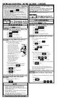
MANUAL OPERATION
The manual release is a device that makes it possible to disconnect
the operator from the gate, thus enabling manual movement.
Before using the release device, cut power to the system, with the
differential switch upstream of the gearmotor.
THE RELEASE DEVICE MUST NOT BE CONSIDERED AN EMERGENCY STOP
If the gate has to be moved manually due to a power cut or fault of the
automated system, use the release device as follows:
1. Fit the supplied key in the lock, Fig. 1 Ref.
, and turn it clockwise as
shown in Fig. 1 Ref.
.
2. Turn the release system clockwise by about 180°, as shown in Fig. 1 Ref.
.
3. Open and close the gate manually.
RESTORING NORMAL OPERATION MODE
To prevent an involuntary pulse from activating the gate during the
manoeuvre, cut power to the system before re-locking the
operator.
1. Turn the release system anti-clockwise by about 180°, as shown in Fig. 2
ref.
.
2. Turn the key anti-clockwise, Fig. 2 ref.
, and remove it from the lock, as
shown in Fig. 2 ref.
.
3. Move the gate until it meshes to release.
Before powering up the system again, make sure that the gate cannot
be moved manually.
MAINTENANCE
To ensure correct long-term operation and a constant level of safety, we
advise you to generally control the system every 6 months. In the “Use
Instructions” booklet, there is a form for recording maintenance jobs.
The enclosed maintenance form is purely a guideline; it cannot
be ruled out that to guarantee a correctly operating automated
system and a constant level of safety, maintenance operations not
described in this form may be necessary.
REPAIRS
The User must not in any way attempt to repair or to take direct action and
must solely contact qualified GENIUS personnel or GENIUS service centres.
FRANÇAIS
Lire attentivement les instructions avant d’utiliser le produit et les
conserver pour toute nécessité future éventuelle
PRESCRIPTIONS GÉNÉRALES DE SÉCURITÉ
S’il est correctement installé et utilisé, l’automatisme
FALCON M
garantit un haut niveau de sécurité. Par ailleurs, quelques règles
simples de comportement peuvent éviter bien des accidents
- Ne pas stationner et interdire aux enfants, aux personnes et aux choses
de stationner près de l’automatisme et en particulier durant le
fonctionnement.
- Éloigner de la portée des enfants les radiocommandes ou tout autre
dispositif générateur d’impulsion, pour éviter que l’automatisme ne
soit actionné involontairement.
- Interdire aux enfants de jouer avec l’automatisme.
- Ne pas contraster volontairement le mouvement du portail.
- Éviter que des branches ou des arbustes n’entravent le mouvement du
portail.
- Faire en sorte que les systèmes de signalisation lumineuse soient
toujours
efficients et bien visibles.
- N’actionner manuellement le portail qu’après l’avoir déverrouillé.
- En cas de dysfonctionnement, déverrouiller le portail pour permettre
l’accès et attendre l’intervention technique du personnel qualifié.
- Lorsque le fonctionnement manuel a été disposé, couper le courant sur
l’installation avant de rétablir le fonctionnement normal.
- N’effectuer aucune modification sur les composants qui font partie du
système d’automation.
- Éviter toute tentative de réparation ou d’intervention directe et s’a-
dresser
uniquement à du personnel qualifié.
- Faire vérifier, au moins tous les six mois, l’efficience de l’automatisme,
des
dispositifs de sécurité et de la mise à la terre par du personnel qualifié.
DESCRIPTION
•
L’automatisme
FALCON M
est l’idéal pour le contrôle des zones d’accès
de véhicules dans un cadre domestique.
•
FALCON M
pour portails coulissants est un opérateur électromécanique
qui transmet le mouvement au vantail par l’intermédiaire d’un pignon à
crémaillère.
•
Pour le comportement détaillé du portail coulissant dans les différentes
logiques de fonctionnement, s’adresser à l’Installateur.
•
Les automatismes disposent de dispositifs de détection d’obstacle
FALCON M_Utente
2
00058I0616 - Rev.1
Summary of Contents for falcon m
Page 1: ...FALCON M...
Page 26: ...FALCON M_Utente 8 00058I0616 Rev 1...
Page 41: ...FALCON M_Utente 8 00058I0616 Rev 1...