background image

Italiano

EN English

FR Français

RU Pусский

FA01085M04

Automazione per cancelli scorrevoli

Serie BXL

BXL04AGS

MANUALE DI INSTALLAZIONE, USO E MANUTENZIONE

Summary of Contents for BXL04AGS

Page 1: ...Italiano EN English FR Fran ais RU P FA01085M04 Automazione per cancelli scorrevoli Serie BXL BXL04AGS MANUALE DI INSTALLAZIONE USO E MANUTENZIONE...

Page 2: ...struzioni nel raggio di azione delle fotocellule Nel caso in cui non sia possibile risolvere il problema seguendo le indicazioni riportate nella tabella o se si riscontrano anomalie malfunzionamenti r...

Page 3: ...Pag 3 Manuale FA01085 IT 02 2018 CAME S p A istruzioni originali...

Page 4: ...ILANCIATO CORRETTAMENTE E SI CHIUDA BENE NEL CASO DI VALUTAZIONE NEGATIVA NON PROCEDERE PRIMA DI AVER OTTEMPERATO AGLI OBBLIGHI DI MESSA IN SICUREZZA ASSICURARSI CHE IL CANCELLO SIA STABILE E CHE LE R...

Page 5: ...O PRIMA DELLA CONSEGNA ALL UTENTE VERIFICARE LA CONFORMIT DELL IMPIANTO ALLA NORMA ARMONIZZATA NELLA DIRETTIVA MACCHINE 2006 42 CE ASSICURARSI CHE L AUTOMAZIONE SIA STATA REGOLATA ADEGUATAMENTE E CHE...

Page 6: ...a 400 kg e 10 m di lunghezza DESTINAZIONE D USO L automazione stata progettata per motorizzare cancelli scorrevoli a uso residenziale o condominiale Ogni installazione e uso difformi da quanto indicat...

Page 7: ...7 Manuale FA01085 IT 02 2018 CAME S p A istruzioni originali IMPIANTO TIPO 1 Automazione 2 Alette di finecorsa 3 Cremagliera 4 Selettore a chiave 5 Lampeggiatore 6 Fotocellule 7 Battuta di arresto 8...

Page 8: ...ve di sblocco INDICAZIONI GENERALI PER L INSTALLAZIONE L installazione deve essere effettuata da personale quali cato ed esperto e nel pieno rispetto delle normative vigenti VERIFICHE PRELIMINARI Prim...

Page 9: ...i possono utilizzare cavi tipo FROR 20 22 II conformi alla EN 50267 2 1 CEI Per il collegamento dell antenna utilizzare cavo tipo RG58 consigliato fino a 5 m Per il collegamento abbinato e CRP utilizz...

Page 10: ...e e i dadi Estrarre le zanche preformate con un cacciavite o una pinza INSTALLAZIONE Le seguenti illustrazioni sono solo esempi in quanto lo spazio per il ssaggio dell automazione e degli accessori va...

Page 11: ...devono passare attraverso i fori predisposti Riempire la cassa matta di cemento la piastra deve essere perfettamente in bolla e con il letto delle viti completamente in super cie Attendere che si sol...

Page 12: ...li Posizionare il motoriduttore sopra la piastra di fissaggio Attenzione I cavi elettrici devono passare sotto la cassa del motoriduttore Forare i passacavi e inserirli nella sede dopo aver fatto pass...

Page 13: ...il pignone del motoriduttore saldare o ssare la cremagliera al cancello in tutta la sua lunghezza Per assemblare i moduli della cremagliera utilizzarne un pezzo di scarto appoggiandolo sotto il punto...

Page 14: ...SA In apertura aprire completamente il cancello infilare l aletta di finecorsa di apertura sulla cremagliera fino a far scattare il micro molla fissarla con i grani In chiusura chiudere completamente...

Page 15: ...i con i trimmer Tutte le connessioni sono protette da fusibili rapidi Fusibili ZN6 Linea 1 6 A F Accessori 2 A F DESCRIZIONE DELLE PARTI 1 DIP 2 Trimmer 3 Pulsante di programmazione 4 LED di segnalazi...

Page 16: ...riduttore 24 V DC Verde Marrone Bianco COLLEGAMENTO MOTORIDUTTORE CON ENCODER E FINECORSA Finecorsa di apertura contatto NC Finecorsa di chiusura contatto NC Lampeggiatore Portata contatto 24 V AC DC...

Page 17: ...o a distanza Pulsante di STOP contatto NC Permette l arresto del cancello con l esclusione della chiusura auto matica Per riprendere il movimento premere il pul sante di comando o un altro dispositivo...

Page 18: ...vimento conseguente ripresa del movimento dopo la rimozione dell ostacolo Se non viene utilizzato il contatto CX va disattivato in programmazione DIP LED rosso PRG PROGRAMMAZIONE DELLE FUNZIONI Tasto...

Page 19: ...Per ritornare all impostazione di default premere di nuovo P1 Il LED lampeggia e il buzzer suona 2 volte Auto apprendimento della corsa parziale Con il pulsante di comando 7 della scheda portare il ca...

Page 20: ...la funzione abilitata Per disabilitarla selezionare i DIP come indicato e premere il tasto P1 sulla scheda Il LED lampeggia e il buzzer suona 2 volte Per ritornare all impostazione di default premere...

Page 21: ...rasmettitore gi stato precedentemente memorizzato il LED lampeggia velocemente e il buzzer suona 4 volte APRE CHIUDE INVERSIONE da trasmettitore Selezionare i DIP come indicato e premere il tasto P1 s...

Page 22: ...o La velocit pu essere regolata dal 30 al 60 della velocit massima SENS Sensibilit Regola la sensibilit di rilevamento degli ostacoli duranteil movimento del cancello Minima sensibilit o massima sensi...

Page 23: ...ONI Il cancello non si apre e non si chiude Manca alimentazione Il motoriduttore sbloccato Il trasmettitore non funziona Il trasmettitore rotto Il pulsante di stop e inceppato o rotto Il pulsante di a...

Page 24: ...I componenti dell imballo cartone plastiche etc sono assimilabili ai rifiuti solidi urbani e possono essere smaltiti senza alcuna difficolt semplicemente effettuando la raccolta differenziata per il...

Page 25: ...Sliding gate operator BXL series BXL04AGS INSTALLATION OPERATION AND MAINTENANCE MANUAL EN English FA01085 EN...

Page 26: ...DO IF ISSUES POSSIBLE CAUSES POSSIBLE FIXES It neither opens nor closes Power supply is missing The gear motor is stuck The transmitter is emitting a weak signal or no signal at all Control buttons o...

Page 27: ...p 3 Manual FA00000 EN 02 2018 CAME S p A Translated original instructions...

Page 28: ...L GREA SED AND THAT IT OPENS AND CLOSES SMOOTHLY THE GUIDE RAIL MUST BE WELL FASTENED TO THE GROUND ENTIRELY ABOVE THE SURFACE AND FREE OF ANY IMPEDIMENTS TO THE GATE S MOVEMENT THE RAILS OF THE UPPER...

Page 29: ...SM CLOSE TO THE MECHANISM MAKE SURE TO HAND OVER TO THE END USER ALL OPERATING MANUALS FOR THE PRODUCTS THAT MAKE UP THE FINAL MACHINERY THE NEXT FIGURE SHOWS THE MAIN HAZARD POINTS FOR PEOPLE Danger...

Page 30: ...up to 400 kg and 10 m in length INTENDED USE The operator is designed to power sliding gates in residential and apartment block settings Do not install of use this device in any way except as speci e...

Page 31: ...p 7 Manual FA00000 EN 02 2018 CAME S p A Translated original instructions DIMENSIONS MM STANDARD INSTALLATION 1 Operator 2 Limit switch fins 3 Rack 4 Key switch selector 5 Flashing light 6 Photocells...

Page 32: ...t the surface is solid enough set up suitable tubes and conduits for the electric cables to pass through making sure they are protected from any mechanical damage TOOLS AND MATERIALS Make sure you hav...

Page 33: ...pliant For power supplies up to 48 V you can use FROR 20 22 II type cables that comply with EN 50267 2 1 CEI To connect the antenna use the RG58 we suggest up to 5 m For paired connection and CRP use...

Page 34: ...eeded for the wiring coming out of the junction pit For connecting the gearmotor we suggest using a 40 mm corrugated tube whereas for the accessories we suggest 25 mm tubes The number of tubes depends...

Page 35: ...n frame with concrete The plate must be perfectly level with the bolts which are entirely above surface Wait at least 24 hrs for the concrete to solidify Remove the foundation frame and ll the hole wi...

Page 36: ...hreading the cables Lift the gearmotor by 5 to 10 mm from the plate by adjusting the threaded steel feet to allow any subsequent adjustments between pinion and rack SETTING UP THE GEARMOTOR Remove the...

Page 37: ...is prevents the gate s weight from bearing down on the operator FASTENING THE RACK If the rack is already set up the next step should be to adjust the rack and pinion coupling distance otherwise faste...

Page 38: ...ten it using the allen screws Don t let the gate get to the mechanical stop whether it is the opening or closing one ESTABLISHING THE LIMIT SWITCH POINTS For opening completely open the gate fit the o...

Page 39: ...terminal 12 Accessories board fuse 13 Antenna terminal 14 AF card slot 15 Green power module terminal 16 R800 card connector 17 Power supply terminal board 18 Line fuse ELECTRICAL CONNECTIONS AND PROG...

Page 40: ...ply output 24 V AC DC max 20 W Control board power supply 24 V AC DC Power supply 230 V AC 50 60 Hz INPUT VOLTAGE Flashing light Contact rating 24 V AC DC 25 W max Closing limit switch NC contact Open...

Page 41: ...N STOP CLOSE STOP command STOP STOP N C contact For stopping the gate while excluding automatic closing To resume mo vement press the control button or use another control device If unused it should b...

Page 42: ...stays on and the buzzer sounds off for one second Press P1 to return to the default parameters The LED blinks and the buzzer sounds off twice P1 key FUNCTIONS PROGRAMMING Red LED PRG DIP SWITCH SAFET...

Page 43: ...e buzzer sounds off for one second To return to the default settings press P1 again The LED blinks and the buzzer sounds off twice Self learningof the partial gate travel Using the control button 7 on...

Page 44: ...function is enabled To disableit select the DIP switches as shown and press the P1 key on the control board The LED blinks and the buzzer sounds off twice To return to the default parameters press P1...

Page 45: ...tter has previously been saved the LED blinks quickly and the buzzer sounds off 4 times Transmitter activated OPEN CLOSE INVERT Select the DIP switches as shown and press the P1 key on the control boa...

Page 46: ...amming phases the automatic closing waiting time and of any errors malfunctions PWR Green It warns about the voltage present in the control board ALERT LED Trimmer Description of functions A C T Autom...

Page 47: ...losing button or the key switch selector is stuck Check main power supply Lock the gearmotor Replace the batteries Call for assistance Call for assistance Call for assistance The gate opens but does n...

Page 48: ...s DISPOSING OF THE PACKAGING The packaging materials cardboard plastic and so on should be disposed of as solid household waste and simply separated from other waste for recycling Always make sure you...

Page 49: ...Automatisme pour portails coulissants S rie BXL BXL04AGS MANUEL D INSTALLATION D UTILISATION ET D ENTRETIEN FR Fran ais FA01085 FR...

Page 50: ...OBL MES CAUSES POSSIBLES REM DES POSSIBLES Le portail ne s ouvre pas et ne se ferme pas Absence d alimentation Le motor ducteur est d bloqu L metteur met un signal faible ou inexistant Boutons ou s le...

Page 51: ...Page 3 Manuel FA00000 FR 02 2018 CAME S p A Traduction des instructions originales...

Page 52: ...TOUT AUTOUR AVANT D INSTALLER L AU TOMATISME S ASSURER DES BONNES CONDITIONS M CANIQUES DU PORTAIL CONTR LER QU IL EST BIEN QUILIBR ET QU IL SE FERME CORRECTEMENT EN CAS D VALUATION N GATIVE NE PROC D...

Page 53: ...S N CESSAIRES AVANT DE LIVRER L INSTALLATION L UTILISATEUR EN CONTR LER LA CONFORMIT LA DIRECTIVE MACHINES 2006 42 CE S ASSURER QUE L AUTOMATISME A BIEN T R GL COMME IL FAUT ET QUE LES DISPOSITIFS DE...

Page 54: ...et 10 m de longueur UTILISATION PR VUE L automatisme a t con u pour motoriser des portails coulissants usage r sidentiel ou collectif Toute installation et toute utilisation autres que celles qui son...

Page 55: ...el FA00000 FR 02 2018 CAME S p A Traduction des instructions originales DIMENSIONS MM INSTALLATION STANDARD 1 Automatisme 2 Ailettes de fin de course 3 Cr maill re 4 S lecteur cl 5 Clignotant 6 Photoc...

Page 56: ...la surface de xation est bien solide pr voir des tuyaux et des conduites pour le passage des c bles lectriques a n de les prot ger contre la d t rioration m canique OUTILS ET MAT RIEL S assurer de di...

Page 57: ...imentations jusqu 48 V il est possible d utiliser des c bles FROR 20 22 II conformes la norme EN 50267 2 1 CEI Pour la connexion de l antenne utiliser un c ble RG58 jusqu 5 m Pour la connexion vis vis...

Page 58: ...es gaines annel es pour les raccordements issus du bo tier de d rivation Il est conseill de pr voir un tuyau annel 40 mm pour la connexion du motor ducteur et des tuyaux 25 mm pour les accessoires Le...

Page 59: ...Remplir le coffrage de ciment la plaque doit tre parfaitement nivel e et avec le let des vis totalement en surface Attendre que le tout se solidi e pendant au moins 24 heures Enlever le coffrage et re...

Page 60: ...le motor ducteur de 5 10 mm de la plaque en intervenant sur les pieds filet s en acier afin de permettre par la suite les ventuels r glages entre pignon et cr maill re PR PARATION DU MOTOR DUCTEUR En...

Page 61: ...e le poids du portail ne p se sur l automatisme FIXATION DE LA CR MAILL RE Si la cr maill re existe d j r gler directement la distance d accouplement pignon cr maill re ou bien effec tuer la xation d...

Page 62: ...xer l aide des goujons viter que le portail n arrive contre la but e d arr t en phase d ouverture comme en phase de fermeture D TERMINATION DES POINTS DE FIN DE COURSE En phase d ouverture ouvrir comp...

Page 63: ...sible accessoires carte 13 Bornier pour antenne 14 Connecteur pour carte AF 15 Bornier pour module Green power 16 Connecteur pour carte R800 17 Bornier 18 Fusible de ligne BRANCHEMENTS LECTRIQUES ET P...

Page 64: ...24 VAC DC max 20 W Alimentation carte lectronique 24 V AC DC Alimentation 230 VAC 50 60 Hz ALIMENTATION Feu clignotant Port e contact 24 V AC DC 25 W max Fin de course de fermeture contact NF Fin de c...

Page 65: ...T depuis la programmation des fonctions Bouton d ARR T contact NF Permet l arr t du portail avec d sactivation de la fermeture automa tique Pour reprendre le mouvement appuyer sur le bouton de comman...

Page 66: ...on des fonctions l entr e CX peut tre configur e en C1 r ouverture durant la fermeture Durant la phase de fermeture du portail l ouverture du contact provoque l inversion du mouvement jusqu ouverture...

Page 67: ...r sonne pendant 1 s Pour revenir la configuration par d faut appuyer de nouveau sur P1 Le voyant clignote et le buzzer sonne 2 fois Auto apprentissage de la course partielle Au moyen du bouton de comm...

Page 68: ...st par d faut activ e Pour la d sactiver s lectionner les commutateurs DIP comme indiqu et enfoncer la touche P1 sur la carte Le voyant clignote et le buzzer sonne 2 fois Pour revenir la configuration...

Page 69: ...onne pendant 1 s En cas d metteur d j m moris le voyant clignote rapidement et le buzzer sonne 4 fois OUVERTURE FERMETURE INVERSION par metteur S lectionner les commutateurs DIP comme indiqu et enfonc...

Page 70: ...e et les ventuelles erreurs anomalies PWR Vert Indique la pr sence de tension dans la carte lectronique VOYANT DE SIGNALISATION LED Trimmers Description des fonctions TFA Temps de fermeture automatiqu...

Page 71: ...ermeture ou le s lecteur cl sont bloqu s Contr ler l alimentation secteur Bloquer le motor ducteur Remplacer les piles S adresser l assistance S adresser l assistance S adresser l assistance Le portai...

Page 72: ...mballage carton plastiques etc sont assimilables aux d chets urbains solides et peuvent tre limin s sans aucune difficult en proc dant tout simplement la collecte diff renci e pour le recyclage Avant...

Page 73: ...BXL BXL04AGS RU FA01085 RU...

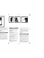
Page 74: ...3 2 1 1 2 3 4 2 FA00000 RU 02 2018 CAME S p A...

Page 75: ...3 FA00000 RU 02 2018 CAME S p A...

Page 76: ...4 FA00000 RU 02 2018 CAME S p A CAME S P A 2006 42 CE 2006 42 CE 2006 42 CE 2 5...

Page 77: ...5 FA00000 RU 02 2018 CAME S p A 3 III 1 85 1 5 2006 42 CE...

Page 78: ...6 FA00000 RU 02 2018 CAME S p A 400 10 BXL04AGS 10 400 4 BXL04AGS IP 44 50 60 230 24 7 7 4 RGP1 1 2 150 50 C 20 55 I 7 7...

Page 79: ...117 211 349 105 160 300 170 298 149 149 1 10 2 2 3 6 6 4 7 8 5 9 7 7 FA00000 RU 02 2018 CAME S p A 1 2 3 4 5 6 7 8 9 10...

Page 80: ...8 10 1 15 16 13 5 4 4 5 7 6 1 9 11 12 3 17 7 6 2 14 8 FA00000 RU 02 2018 CAME S p A 1 2 3 4 5 UNI 5739 M12X60 6 12 7 UNI 5588 M12 8 9 10 11 12 13 14 EMC02 15 16 17...

Page 81: ...CAME S p A 20 20 30 230 1P N PE 3G x 1 5 2 3G x 2 5 2 2 x 0 5 2 2 x 0 5 2 2 x 0 5 2 2 x 0 5 2 230 H05RN F 60245 IEC 57 IEC H05VV F 60227 IEC 53 IEC 48 FROR 20 22 II EN 50267 2 1 CEI RG58 5 CRP UTP CAT...

Page 82: ...3 0 0 4 5 0 40 0 50 2 UNI 5734 12 UNI 5588 M12 10 FA00000 RU 02 2018 CAME S p A 40 25 50...

Page 83: ...95 105 11 FA00000 RU 02 2018 CAME S p A 600 24...

Page 84: ...2 1 5 10 2 1 3 12 FA00000 RU 02 2018 CAME S p A 5 10...

Page 85: ...1 2 13 FA00000 RU 02 2018 CAME S p A...

Page 86: ...1 2 1 2 14 FA00000 RU 02 2018 CAME S p A...

Page 87: ...1 2 3 4 5 16 14 15 11 12 6 9 10 7 8 13 17 18 15 FA00000 RU 02 2018 CAME S p A 1 DIP 2 3 4 5 7 6 7 8 9 10 11 12 13 14 AF 15 Green ower 16 R800 17 18 24 10 11 20 DIP ZN6 1 6 A 2 A...

Page 88: ...24 0 10 11 E L N CX E FC FA F M N 10 11 E M 16 FA00000 RU 02 2018 CAME S p A 24 20 24 230 50 60 24 25 24...

Page 89: ...A B 1 2 3P 7 10 TS 2 R800 OK 17 FA00000 RU 02 2018 CAME S p A R800 R800 AF AF868 AF43S RG58 AF R800...

Page 90: ...TX 2 TX 2 10 2 TX C NC DN10 TX 2 TX 2 10 2 TX C NC DN10 18 FA00000 RU 02 2018 CAME S p A DIP OFF 25 DIP P1 PRG DIP CX CX C1 C4 CX DIP P1 1 P1 2...

Page 91: ...19 FA00000 RU 02 2018 CAME S p A 1 2 DIP P1 2 P1 1 DIP P1 1 4 P1 2 CX DIP P1 1 P1 2 2 CX DIP P1 1 P1 2 7 DIP P1 1 P1 2 4 2 7 DIP P1 1 P1 2 DIP P1 1 P1 2 A C T...

Page 92: ...20 FA00000 RU 02 2018 CAME S p A DIP P1 2 P1 1 2 7 DIP P1 1 P1 2 DIP P1 1 P1 2 DIP P1 2 P1 1 DIP P1 1 P1 2 2 3P 2 7 5 DIP P1 1 P1 2 100 40 DIP P1 1 P1 2...

Page 93: ...21 FA00000 RU 02 2018 CAME S p A A C T SP SLOW SENS DIP P1 1 DIP P1 10 1 4 DIP P1 10 1 4 DIP P1 10 1 4 DIP P1 10 1 4 DIP P1 5 1 DIP P1 2 25...

Page 94: ..._ A C T _ SP SLOW _ SENS A C T SP SLOW SENS CX 3P PWR 1 PRG 7 22 FA00000 RU 02 2018 CAME S p A LED CX 2 CX 1 1 2 3P 2 3 7 2 7 PRG PWR A C T 1 120 SP SLOW 30 60 SENS...

Page 95: ...2 1 23 FA00000 RU 02 2018 CAME S p A...

Page 96: ...CAME S p A Via Martiri Della Libert 15 31030 Dosson di Casier Treviso Italy tel 39 0422 4940 fax 39 0422 4941 FA00000 RU 02 2018 CAME S p A CAME S p A UNI EN ISO 14001...

Reviews: