1
DOOR Series -
English
INSTALLATION GUIDE
DOOR
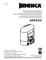
Automation for sliding automatic door
Via Enrico Fermi, 43 - 36066 Sandrigo (VI) Italia
Tel +39 0444 750190 - Fax +39 0444 750376 - [email protected] - www.tauitalia.com
D-MNL0DOOR-GB
26-01-2016
- R
ev
.22
GB - Translation of Original Instructions