8-12
745 Transformer Management Relay
GE Multilin
8.5 PROTECTION SCHEMES
8 COMMISSIONING
8
8.5PROTECTION SCHEMES
8.5.1 PRECAUTIONS
Keep track of modifications/changes made to settings during the course of these commissioning steps
and ensure that all settings are returned to the "in-service" values at the end of the tests.
8.5.2 HARMONIC RESTRAINED PERCENT DIFFERENTIAL
The harmonic restrained percent differential element setpoints are located in
S4 ELEMENTS
ÖØ
DIFFERENTIAL
Ö
PERCENT
DIFFERENTIAL
. Disable all other protection elements to ensure that trip relay(s) and auxiliary relays are operated by element
under test only. With a multimeter, monitor the appropriate output contact(s) per intended settings of the FlexLogic™. Refer
to the relay settings to find out which relay(s) should operate when a given element operates.
a) MINIMUM PICKUP
1.
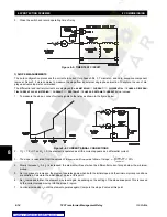
The minimum pickup of the Phase A element is measured by applying a fundamental frequency AC current to termi-
nals H1 and G1, Winding 1 Phase A. Monitor the appropriate trip and auxiliary contact(s) as the current is increased
from 0 A. Compare the current value at which operation is detected against the
S4 ELEMENTS
ÖØ
DIFFERENTIAL
Ö
PER-
CENT DIFFERENTIAL
ÖØ
PERCENT DIFFERENTIAL PICKUP
setpoint. Since the operating point is normally set quite low,
fine control of the current signal will be required to obtain accurate results.
2.
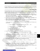
The currents in the winding may be phase shifted or may have the zero-sequence component removed due to auto-
configuration (see Section 5.2: Auto-Configuration on page 5–5). As an alternate to calculating to relation of input cur-
rent to differential current, the differential current is displayed in
A2 METERING
Ö
CURRENT
ÖØ
DIFFERENTIAL
. Ensure
that the displayed value is the same as the minimum pickup setting when the element operates.
3.
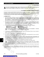
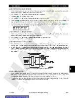
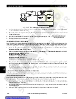
Check that the Trip and Message LEDs are flashing and one of the following trip messages is displayed:
The above message will indicate either
OPERATED
or
LATCHED
depending on the
S4 ELEMENTS
ÖØ
DIFFEREN-
TIAL
Ö
PERCENT DIFFERENTIAL
ÖØ
PERCENT DIFFERENTIAL TARGET
setting.
4.
To independently verify that auto-configuration causes the currents to be as measured, follow the rules outlined in
Steps 5 to 9 below.
5.
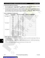
Look up transformer type in Table 5–1: Transformer Types on page 5–10.
6.
For the phase shift shown for the particular set of vectors, determine the processing applied to the current vectors for
that winding from Table 5–2: Phase Shifts on page 5–22.
7.
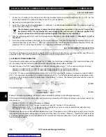
Calculate the “dashed” current values using the equations in Table 5–2: Phase Shifts on page 5–22. If applicable, use
the zero-sequence removal computation. This is applicable for all Delta windings and for both windings of a wye-wye
transformer. Compute the processed current vectors to obtain the “dashed” values for that winding.
8.
Calculate the CT correction factor for Windings 2 (and 3 if applicable) and apply as necessary.
9.
Turn the equations around to compute the threshold differential currents in terms of the applied currents.
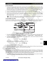
To check the threshold without performing computations, inject balanced 3-phase currents into any winding.
With balanced conditions, there is no effect on magnitude due to phase shifting and zero-sequence removal
has no effect. However, the CT ratio mismatch is still applicable.
10. Repeat the minimum pickup level measurements for the Phase B (inputs H2 and G2) and the Phase C element (inputs
H3 and G3).
The above tests have effectively verified the minimum operating level of the three harmonic restrained differential elements.
If desired the above measurements may be repeated for the phase inputs for the other winding(s). The results should be
identical.
LATCHED a
Percent Differentl
OPERATED a
Percent Differentl
CAUTION
NOTE
NOTE

