GE Multilin
745 Transformer Management Relay
8-1
8 COMMISSIONING
8.1 GENERAL
8
8 COMMISSIONING 8.1GENERAL
8.1.1 INTRODUCTION
The procedures contained in this section can be used to verify the correct operation of the 745 Transformer Management
Relay prior to placing it into service for the first time. These procedures may also be used to verify the relay on a periodic
basis. Although not a total functional verification, the tests in this chapter verify the major operating points of all features of
the relays. Before commissioning the relay, users should read Chapter 3: Installation, which provides important information
about wiring, mounting, and safety concerns. The user should also become familiar with the relay as described in Chapter
2: Getting Started and Chapter 5: Setpoints.
Test personnel must be familiar with general relay testing practices and safety precautions to avoid personal injuries or
equipment damage.
This chapter is divided into several sections, as follows:
•
GENERAL
: outlines safety precautions, conventions used in the test procedures.
•
TEST EQUIPMENT
: the test equipment required.
•
GENERAL PRELIMINARY WORK
•
LOGIC INPUTS AND OUTPUT RELAYS
: tests all digital and analog inputs, the A/D data acquisition system, and relay
and transistor outputs.
•
DISPLAY, METERING, COMMUNICATIONS, ANALOG OUTPUTS
: tests all values derived from the AC current and
voltage inputs.
•
PROTECTION SCHEMES
: tests all features that can cause a trip, including differential, overcurrent, over and under-
frequency elements.
•
AUXILIARY PROTECTION/MONITORING FUNCTIONS
•
PLACING
RELAY INTO SERVICE
•
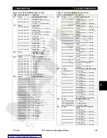
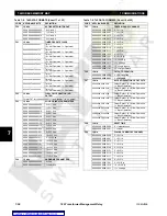
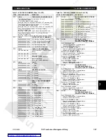
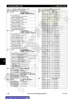
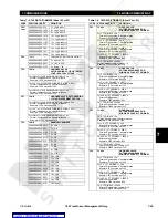
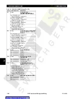
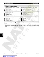
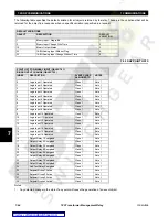
SETPOINT TABLES
8.1.2 TESTING PHILOSOPHY
The 745 is realized with digital hardware and software algorithms, using extensive internal monitoring. Consequently, it is
expected that, if the input circuits, CTs, VTs, power supply, auxiliary signals, etc., are functioning correctly, all the protection
and monitoring features inside the relay will also perform correctly, as per applied settings. It is therefore only necessary to
perform a calibration of the input circuits and cursory verification of the protection and monitoring features to ensure that a
fully-functional relay is placed into service.
Though tests are presented in this section to verify the correct operation of all features contained in the 745, only those fea-
tures which are placed into service need be tested. Skip all sections which cover features not included or not enabled when
the relay is in service, except for the provision of the next paragraph.
Some features such as the Local/Remote Reset of targets, display messages and indications are common to all the protec-
tion features and hence are tested only once. Testing of these features has been included with the Harmonic Restraint Per-
cent Differential, which will almost always be enabled. If, for some reasons, this element is not enabled when the relay is in
service, you will need to test the Local/Remote Reset when testing another protection element.

