GE Multilin
745 Transformer Management Relay
6-5
6 ACTUAL VALUES
6.3 A2 METERING
6
6.3A2 METERING
6.3.1 CURRENT
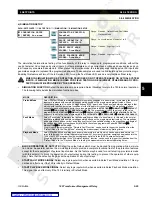
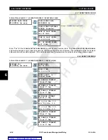
a) MAIN MENU
PATH: ACTUAL VALUES
ÖØ
A2 METERING
Ö
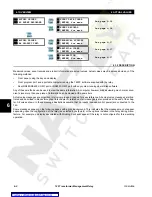
CURRENT
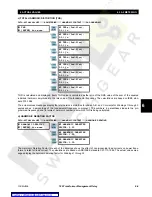
For each monitored winding, the fundamental frequency magnitude and phase angle of phase A, B, C and ground currents
are recalculated every half-cycle for use in differential and overcurrent protection. From these values, neutral, positive, neg-
ative and zero-sequence as well as differential, restraint and ground differential currents are calculated. These are dis-
played and updated approximately twice a second for readability.
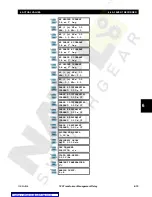
b) WINDING CURRENTS
PATH: ACTUAL VALUES
ÖØ
A2 METERING
Ö
CURRENT
Ö
W1(3) CURRENT
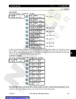
The fundamental frequency current magnitudes for Winding 1 phases A, B, and C, neutral, and ground are shown. The cur-
rent angle for Phase A is always set to 0° as it is used as reference for all other currents, both measured and derived. The
maximum specified load and average phase current are also shown for the specified winding.
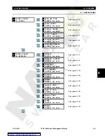
CURRENT
[ENTER] for more
W1 CURRENT
[ENTER] for more
See below.
W2 CURRENT
[ENTER] for more
W3 CURRENT
[ENTER] for more
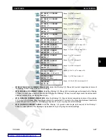
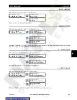
POSITIVE SEQUENCE
[ENTER] for more
See page 6–6.
NEGATIVE SEQUENCE
[ENTER] for more
See page 6–6.
ZERO SEQUENCE
[ENTER] for more
See page 6–6.
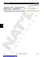
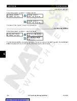
DIFFERENTIAL
[ENTER] for more
See page 6–7.
RESTRAINT
[ENTER] for more
See page 6–7.
GND DIFFERENTIAL
[ENTER] for more
See page 6–7.
W1 CURRENT
[ENTER] for more
W1 PHASE A CURRENT:
0 A at
0° Lag
W1 PHASE B CURRENT:
0 A at
0° Lag
W1 PHASE C CURRENT:
0 A at
0° Lag
W1 NEUTRAL CURRENT:
0 A at
0° Lag
W1 GROUND CURRENT:
0 A at
0° Lag
WINDING 1 LOADING:
0% of rated load
W1 AVERAGE PHASE
CURRENT:
0 A
ENTER
ESCAPE
ð
ð
MESSAGE
ESCAPE
MESSAGE
ESCAPE
MESSAGE
ESCAPE
MESSAGE
ESCAPE
MESSAGE
ESCAPE
MESSAGE
ESCAPE
MESSAGE
ESCAPE
MESSAGE
ESCAPE
ENTER
ESCAPE
ð
ð
MESSAGE
ESCAPE
MESSAGE
ESCAPE
MESSAGE
ESCAPE
MESSAGE
ESCAPE
MESSAGE
ESCAPE
MESSAGE
ESCAPE

