[130] Pump 1
Interlock
[131] Pump 2
Interlock
[132] Pump 3
Interlock
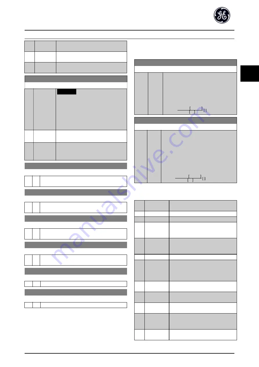
E-00 Digital I/O Mode
Option:
Function:
NOTICE
This parameter cannot be adjusted
while the motor is running.
Digital inputs and programmed digital
outputs are pre-programmable for operation
either in PNP or NPN systems.
[0]
*
PNP - Active
at 24V
Action on positive directional pulses (0). PNP
systems are pulled down to GND.
[1]
NPN - Active
at 0V
Action on negative directional pulses (1).
NPN systems are pulled up to +24 V,
internally in the frequency converter.
E-01 Terminal 18 Digital Input
Option: Function:
Same options and functions as E-0#, except for
Pulse
input
.
E-02 Terminal 19 Digital Input
Option: Function:
Same options and functions as E-0#, except for
Pulse
input
.
E-03 Terminal 27 Digital Input
Option: Function:
Same options and functions as parameter group E-0#,
except for
Pulse input
.
E-04 Terminal 29 Digital Input
Option: Function:
Same options and functions as parameter group E-0#,
except for
Pulse input
.
E-05 Terminal 32 Digital Input
Option: Function:
Same options and functions as parameter group E-0#.
E-06 Terminal 33 Digital Input
Option: Function:
Same options and functions as parameter group. E-0#.
3.3.1 E-1# Additional Accel Decel Ramps
Choosing ramp parameters.
E-10 Accel Time 2
Range:
Function:
10.00
s
*
[1.00 -
3600 s]
Enter the accel time, that is the acceleration
time from 0 RPM–
Select a accel time such that the output
current does not exceed the current limit in
during ramping.
See decel time in
.
par
.
E
− 10 =
tacc
×
nnom
par
.
P
− 06
ref
rpm
s
E-11 Decel Time 2
Range:
Function:
20.00
s
*
[1.00
- 3600
s]
Enter the decel time, that is the deceleration
time from
–0 RPM.
Select a decel time such that no overvoltage
arises in the inverter due to regenerative
operation of the motor, and such that the
generated current does not exceed the current
limit set in
. See
accel time in
.
par
.
E
− 11 =
tdec
×
nnom
par
.
P
− 06
ref
rpm
s
3.3.2 E-2# Digital Outputs
[0]
*
No operation
Default for all digital outputs and relay
outputs.
[1]
Control ready
The control board receives supply voltage.
[2]
Drive ready
The control board receives supply voltage.
[3]
Drive rdy/rem
ctrl
The frequency converter is ready for
operation and applies a supply signal on
the control board.
[4]
Standby / no
warning
Ready for operation. No start or stop
command is been given (start/disable).
There are no warnings.
[5]
Running
Motor is running.
[6]
Running / no
warning
Output speed is higher than the speed set
in
parameter H-81 Min Speed for Function at
. The motor is running and there
are no warnings.
[8]
Run on ref/no
warn
Motor runs at reference speed.
[9]
Alarm
An alarm activates the output. There are
no warnings.
[10]
Alarm or
warning
An alarm or a warning activates the
output.
[11]
At torque
limit
The torque limit set in
parameter F-40 Torque Limiter (Driving)
has
been exceeded.
[12]
Out of current
range
The motor current is outside the range set
in
parameter F-43 Current Limit
.
Parameter Description
AF-600 FP
™
Programming Guide
DET-620D
03/2016 All rights reserved.
45
3
3


