
190-01115-01
G3X/G3X Touch Installation Manual - GSU 25/25B Installation
Rev. AC
Page 18-6
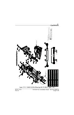
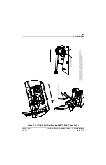
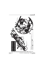
18.4.3 Unit Mounting
For final installation and assembly, refer to the outline and installation drawing
and
of this manual.
1. Mount the unit to a suitable mounting location using the hardware in the connector kit (
per the requirements in
.
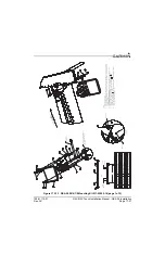
2. Assemble the wiring harness and backshell connectors
3. Assemble the pneumatic hoses and connectors.
4. Connect backshell connector and hoses.
5. Connect CAN terminator to unit if required (see
NOTE
When mounting the GSU 25 to the airframe, it is important to ensure that fastening
hardware is tight for proper unit operation.
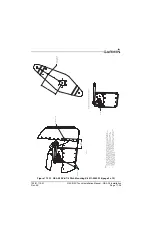
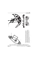
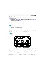
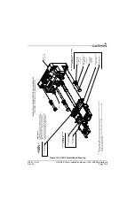
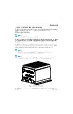
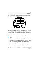
18.4.4 Pneumatic Plumbing
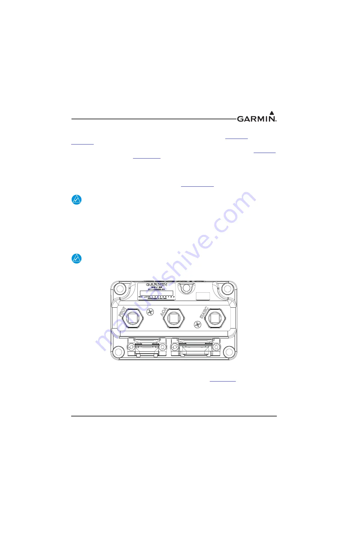
The GSU 25 has three ports that are connected to the aircraft’s pitot pressure source, static pressure source,
and AOA (Angle Of Attack). The ports are labeled on the unit (Figure 18-3). The pressure ports have 1/8-
27 ANPT female threads. The mating fitting must have 1/8-27 ANPT male threads.
NOTE
The temporary port plugs attached to the pressure ports on a new GSU 25 are not suitable
for flight, remove prior to installation of GSU 25 into aircraft.
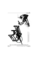
Figure 18-3 GSU 25 Air Hose Fitting Locations
Use appropriate air hoses and fittings to connect the pitot and static lines to the unit. Use colored (or well
marked) tubing to avoid confusing pitot, static, and AOA plumbing per
. Avoid sharp bends
and routing near aircraft control cables. The GSU 25 should not be at the low point of the pneumatic
plumbing lines, to avoid moisture or debris collecting at or near the unit. Ensure that no deformations of
the airframe surface have been made that would affect the relationship between static air pressure and true
ambient static air pressure for any flight condition. Refer to part 43, Appendix E for approved practices
while installing hoses and connections.


