


190-01115-01
G3X/G3X Touch Installation Manual - GEA 24 Installation
Rev. AC
Page 10-3
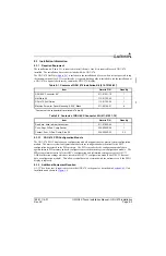
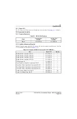
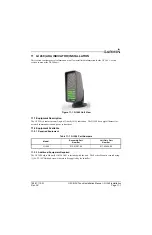
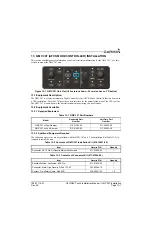
10.3 General Specifications
See
for power/current specifications, and
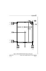
for dimension/weight specifications.
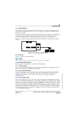
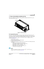
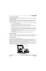
10.4 Unit Installation
Fabrication of a wiring harness is required. Sound mechanical and electrical methods and practices are
recommended for installation of the GEA 24. Refer to
for wiring considerations, and to
for pinouts.
The GEA 24 connects to other LRUs in the G3X system using the CAN bus. To provide an optional
redundant path for engine data, a secondary RS-232 connection to a single GDU display is also supported.
See
for wiring and configuration information.
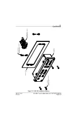
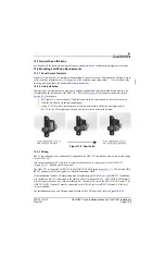
1. Mount the unit to a suitable mounting location using (4) #10-32 pan or hex head screws.
2. Assemble the connector backshells and wiring harness.
3. Connect CAN terminator to unit if required (
).
4. Connect backshell connectors.
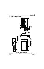
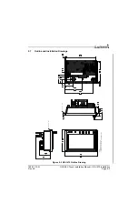
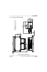
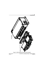
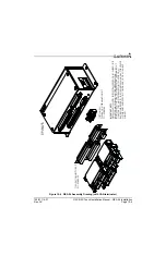
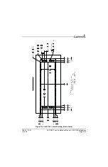
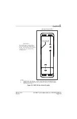
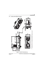
10.5 Mounting Requirements
The GEA 24 will mount remotely. The GEA 24 will be secured to the airframe using four #10-32 pan or
hex head screws supplied by the installer.
CAUTION
Do not mount the GEA 24 on the ‘hot’ side (engine side) of the firewall, or in any location
where it would be exposed to radiated heat from the engine.


