


190-01115-01
G3X/G3X Touch Installation Manual - LRU Pinouts
Rev. AC
Page 25-32
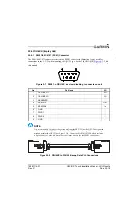
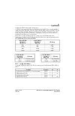
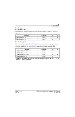
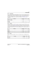
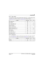
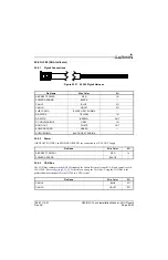
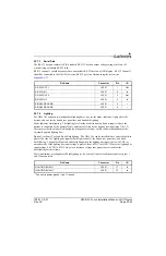
25.5.5
Aircraft Power
The GEA 24 has two pins for aircraft power inputs of 14/28 Vdc, and can operate using power from one or
both inputs (AIRCRAFT POWER 1 AND AIRCRAFT POWER 2). The pins are internally connected
using diodes to prevent current from flowing between the two power inputs. AIRCRAFT POWER 2 is for
connecting to an alternate power source, such as on aircraft with two electrical buses. The two aircraft
power inputs may optionally be used to monitor aircraft bus voltage (see
for
configuration)
.
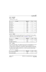
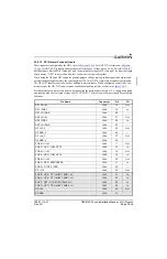
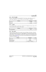
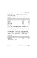
25.5.6
CAN Bus
Both data buses conform to the BOSCH standard for Controller Area Network 2.0-B. The busses comply
with ISO 11898. Refer to
for details on configuring and terminating the CAN bus. The
CAN bus on J241 shall be used for communications between G3X LRUs. The CAN 2 bus on J244 shall be
used to communicate with FADEC engine controllers and shall not be connected to other G3X LRUs. The
CAN2 bus is not terminated at the unit, refer to the wiring diagrams for how to terminate the second CAN
bus if used.
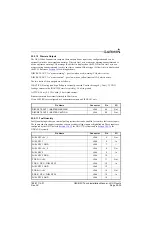
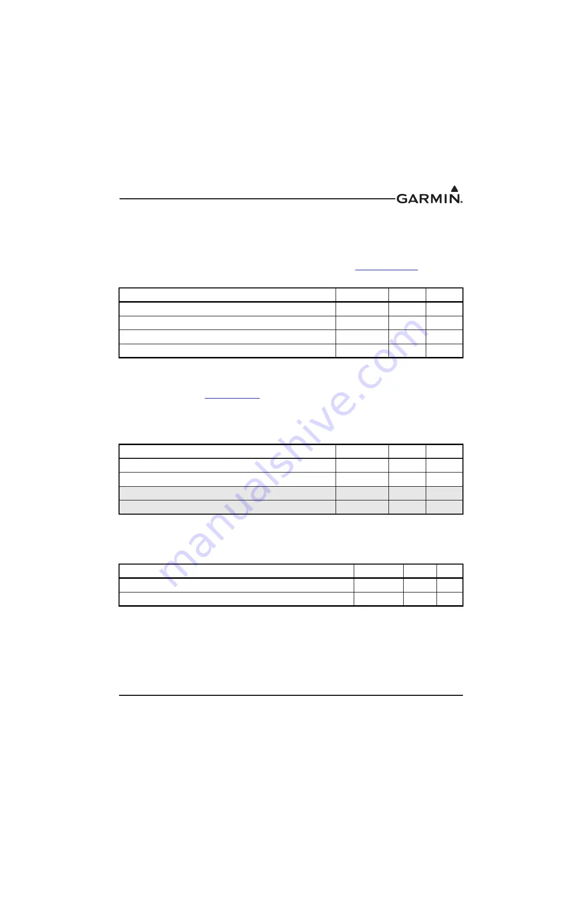
25.5.7
RS-232
The RS-232 channel can optionally be connected to a GDU display to provide a redundant path for EIS
data.
Pin Name
Connector
Pin
I/O
AIRCRAFT POWER 1
J241
7
In
AIRCRAFT POWER 2
J241
8
In
GROUND
J241
6
--
GROUND
J241
9
--
Pin Name
Connector
Pin
I/O
CAN HI
J241
1
I/O
CAN LO
J241
2
I/O
CAN2_HI
J244
17
I/O
CAN2 LO
J244
33
I/O
Pin Name
Connector
Pin
I/O
RS-232 RX
J241
4
In
RS-232 TX
J241
5
Out


