190-01115-01
G3X/G3X Touch Install Manual - GDU 4XX Config and Post Install Checkout
Rev. AC
Page 34-63
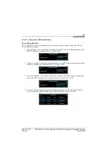
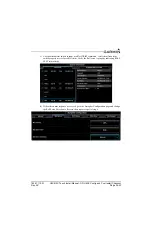
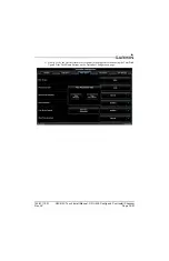
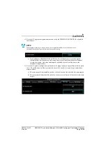
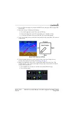
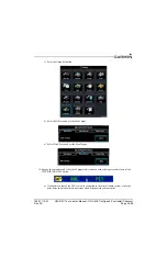
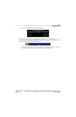
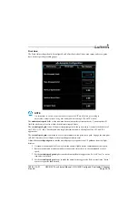
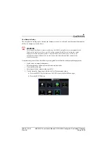
11. Go to the AP page in configuration mode and navigate to the Yaw Damper Servo sub-section to
configure the servo direction.
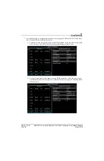
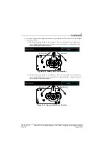
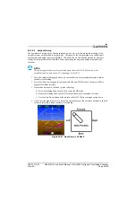
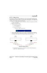
a) The Yaw Damper Servo Direction should be set to Normal. The servo arm should move
clockwise to cause a nose left rudder movement and servo arm should move
counterclockwise to cause a nose right rudder movement.
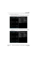
Figure 34-19 Normal Yaw Damper Direction
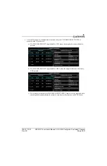
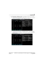
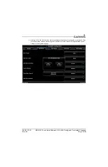
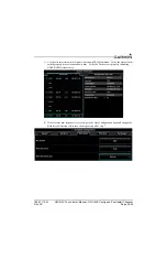
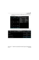
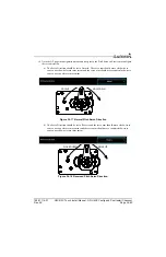
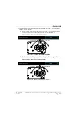
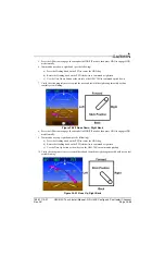
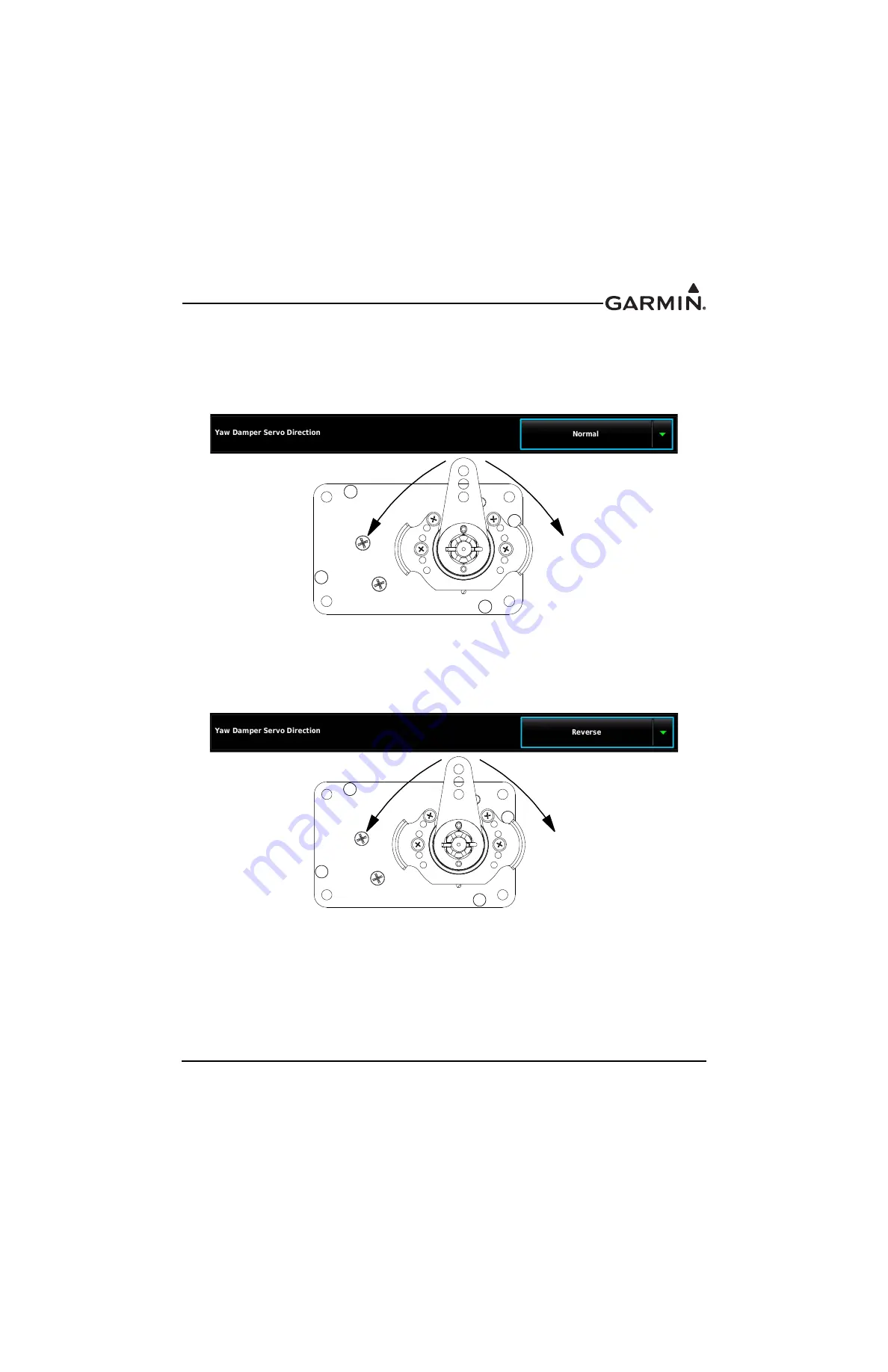
b) The Yaw Damper Servo Direction should be set to Reverse. The servo arm should move
clockwise to cause a nose right rudder movement and the servo arm should move
counterclockwise to cause a nose left rudder movement.
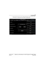
Figure 34-20 Reversed Yaw Damper Direction
NOSE LEFT
NOSE RIGHT
NOSE LEFT
NOSE RIGHT


