


190-01115-01
G3X/G3X Touch Installation Manual - LRU Pinouts
Rev. AC
Page 25-35
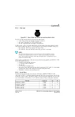
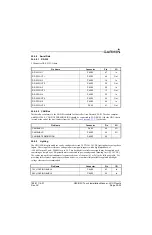
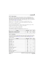
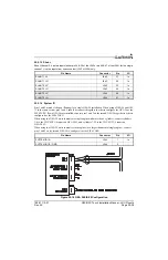
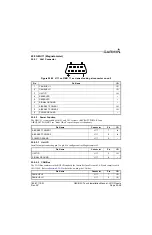
25.5.10 Discrete Outputs
The GEA 24 has 2 annunciator outputs, these outputs do not require any configuration and can be
optionally wired to an external annunciator. Discrete Out 1 acts as a master warning annunciator and is
active any time a warning CAS message (Red Alert) is displayed on the PFD. Discrete Out 2 acts as a
master caution annunciator and is active any time a caution CAS message (Yellow Alert) is displayed on
the PFD. Reference
DISCRETE OUT 1 is "master warning" - goes low when a red (warning) CAS alert is active.
DISCRETE OUT 2 is "master caution" - goes low when a yellow (caution) CAS alert is active.
The two states of these outputs are as follows:
INACTIVE: Floating (can be pulled up to externally sourced Vout in the range 0
≤
Vout
≤
33 VDC)
Leakage current in the INACTIVE state is typically
≤
10 uA to ground
ACTIVE: Vout
≤
0.5 VDC with
≤
20 mA sink current
Sink current must be externally limited to 20 mA max
If two EIS LRUs are configured, use annunciator outputs on EIS LRU#1 only.
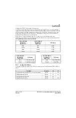
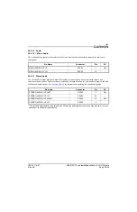
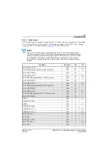
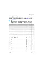
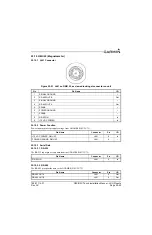
25.5.11 Fuel Quantity
Fuel Quantity inputs have an internal pull-up resistor that can be enabled for resistive fuel sensor inputs.
The inputs can also support capacitive sensors as either voltage inputs or digital inputs. These inputs are
configured by the GDU (refer to
GDU 4XX systems).
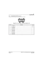
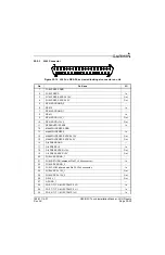
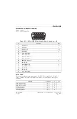
Pin Name
Connector
Pin
I/O
DISCRETE OUT 1 / MASTER WARNING
J244
44
Out
DISCRETE OUT 2 / MASTER CAUTION
J244
45
Out
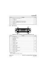
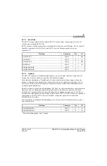
Pin Name
Connector
Pin
I/O
FUEL QTY +5V_1
J244
5
Out
FUEL QTY 1
J244
6
In
FUEL QTY 1 GND
J244
7
--
FUEL QTY +5V_2
J244
8
Out
FUEL QTY 2
J244
9
In
FUEL QTY 2 GND
J244
10
--
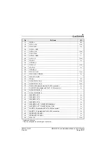
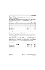
POS 3 HI / +5V
J244
11
Out
POS 3 / GP 3 / FUEL QTY 3
J244
12
In
FUEL QTY 3 GND
J244
13
--
POS 4 HI / +5V
J244
14
Out
POS 4 / GP 4 / FUEL QTY 4
J244
15
In
FUEL QTY 4 GND
J244
16
--


