

190-01115-01
G3X/G3X Touch Installation Manual - Installation Preparation
Rev. AC
Page 2-6
2.1.1.8 GPS
Each GDU display includes an internal VFR GPS receiver, and a connection for an external antenna. GPS
position data is shared between GDU displays via the CAN bus. For a list of GPS antennas supported by
the GDU display, refer to
The GPS 20A is a TSO-compliant WAAS GPS position source that is compatible with the G3X system.
The GPS 20A provides GPS data to the G3X system via the CAN bus, and can send ADS-B position data
to a transponder via RS-232. For GPS 20A installation information and a list of supported GPS antennas,
refer to
.
GPS data is used for ADAHRS performance monitoring, so at least one source of GPS data is required.
This requirement can be met by installing a GPS 20A, or by connecting a GPS antenna to at least one GDU
GPS receiver. In a system with multiple GDU displays, additional GPS antennas may be connected to the
other displays for redundancy, if desired.
The G3X system is capable of displaying basic position data from an external IFR GPS navigator, but this
data is not used for ADAHRS monitoring and thus does not satisfy the above requirement.
For general GPS antenna installation information, refer to
2.1.1.9 ARINC 429
ARINC 429 is an industry-standard data bus format that is primarily used with IFR GPS or GPS/NAV
receivers (see below). The GAD 29 is the primary ARINC 429 data adaptor for the G3X system; the
GSU 73 also supports ARINC 429 input/output. ARINC 429 data is relayed to and from the rest of the
G3X system via the CAN bus. For GAD 29 installation information, refer to
.
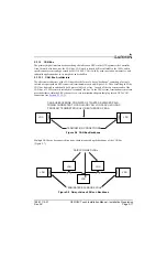
2.1.1.10 Navigation
Basic VFR GPS navigation with the G3X system is performed by the GDU displays, using their internal
navigation databases in conjunction with GPS data from GDU GPS receivers or the GPS 20A. Flight plan
entry and modification is also performed via the GDU displays. For VFR operations, no other source of
navigation data is required.
The G3X system also supports up to two external navigation sources. Supported external navigation
sources include IFR GPS, VHF NAV, and GPS/NAV receivers.
Lateral and vertical deviation (CDI/VDI) and status data from external navigators is displayed on the GDU
displays, as well as external GPS navigator flight plan information. On-screen controls allow switching the
current source of navigation data between multiple external sources, as well as to the G3X system’s
internal flight plan for VFR navigation.
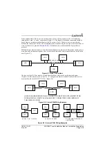
The Garmin GTN 6XX/7XX and GNS 4XX/5XX IFR GPS navigators are supported by the G3X system,
including WAAS approach capability. GPS navigation data is provided to the G3X system via one RS-232
input and one ARINC 429 input for each GTN/GNS unit. The G3X system sends flight data and selected
course information back to the external GPS navigator via an ARINC 429 output.
The G3X system uses an additional ARINC 429 input to receive VOR, localizer, and glideslope deviation
information from a Garmin GTN 650/750 or GNS 430/480/530 IFR GPS/NAV receiver.
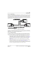
VOR, localizer, and glideslope information from a Garmin GNC 255 or SL30 VHF NAV receiver is also
supported. These radios connect to the G3X system via an RS-232 connection to a GDU display.
When two external navigation sources are connected to the G3X system, the determination of which
source is #1 and which is #2 is determined by the ordering of the RS-232 connections to the GDU displays.
The #1 navigation source should be connected to a lower-numbered RS-232 port on the PFD1 GDU, and


