

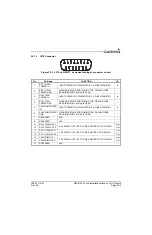
190-01115-01
G3X/G3X Touch Installation Manual - Connector Installation Instructions
Rev. AC
Page 24-9
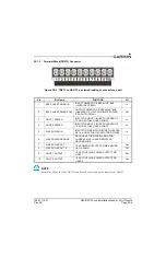
24.4.2 Shield Termination Technique – Method A.1 (Standard)
NOTE
For the following steps please refer to
1. The appropriate number of Jackscrew Backshells will be included in the particular LRU connector
kit.
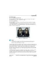
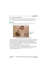
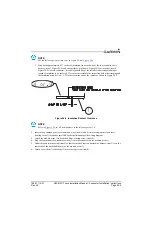
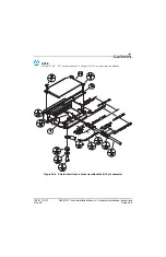
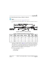
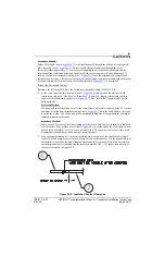
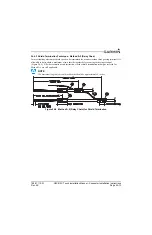
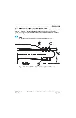
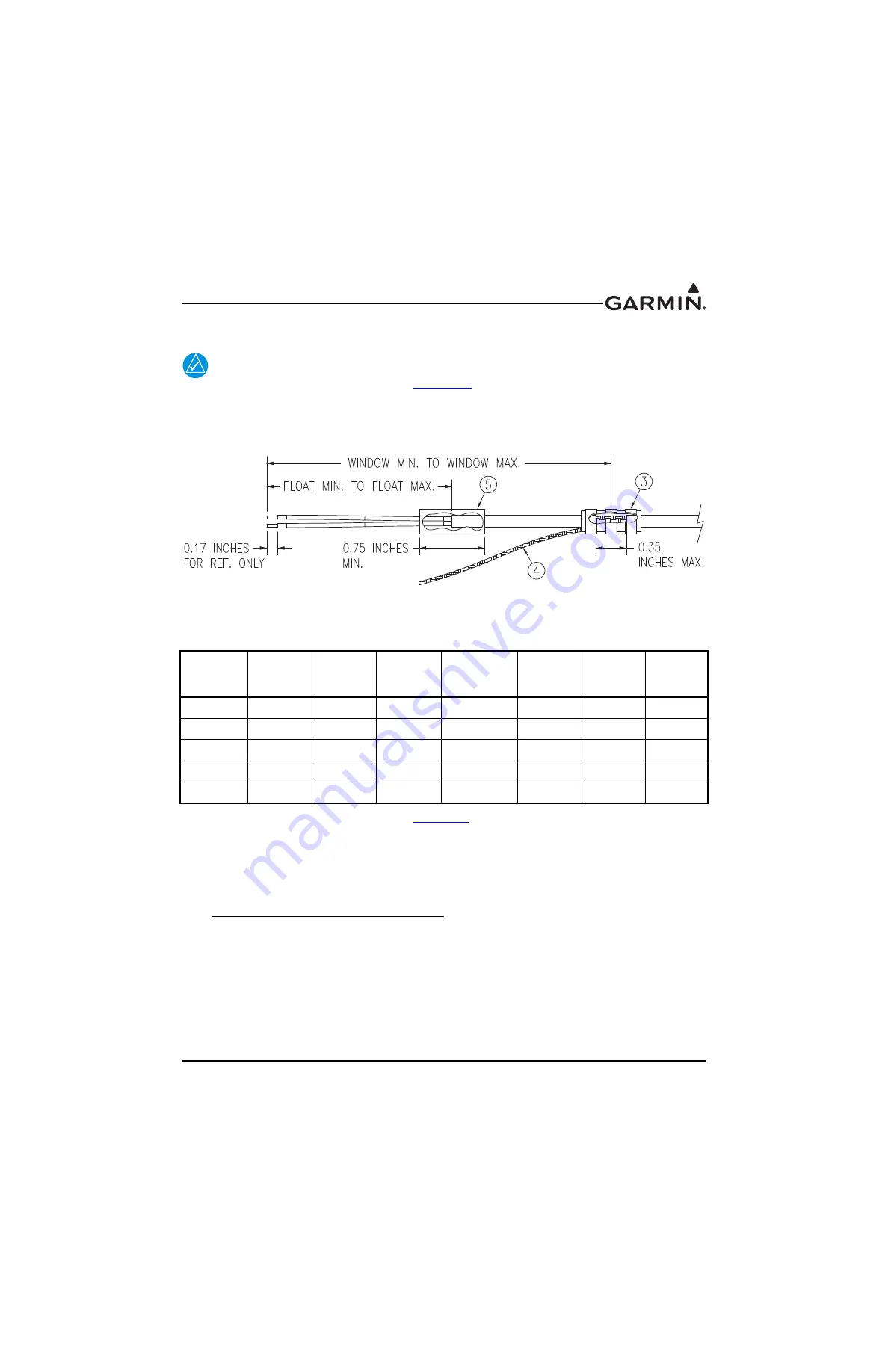
Figure 24-7 Method A.1 for Shield Termination
2. At one end of a shielded cable (item 2,
) measure a distance between “Window Min” to
“Window Max” (Table 24-7) and cut a window (max size 0.35”) in the jacket to expose the shield
(item 4, Figure 24-7). Use caution when cutting the jacket to avoid damaging the individual braids
of the shield. When dealing with a densely populated connector with many cables, it may prove
beneficial to stagger the windows throughout the “Window Min” to “Window Max” range. If
staggering is not needed the “Ideal Window” length is recommended.
Suggested tools to accomplish the window cut:
•
Coaxial Cable Stripper
•
Thermal Stripper
•
Sharp Razor Blade
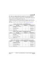
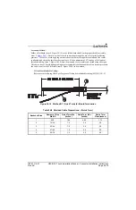
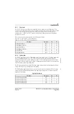
Table 24-7 Shielded Cable Preparations for Garmin Connectors
Backshell-
Size
Number
of Pins
Std/HD
Float Min
(inches)
Float Max
(inches)
Ideal Float
(inches)
Window
Min
(inches)
Window
Max
(inches)
Ideal
Window
(inches)
1
9/15
1.25
2.25
1.75
2.75
5.25
4.25
2
15/26
1.5
2.5
2.0
3.0
5.5
4.5
3
25/44
1.5
2.5
2.0
3.0
5.5
4.5
4
37/62
1.5
2.5
2.0
3.0
5.5
4.5
5
50/78
1.5
2.5
2.0
3.0
5.5
4.5


