190-01115-01
G3X/G3X Touch Installation Manual - GAD 29 Installation
Rev. AC
Page 4-1
4 GAD 29 (ARINC 429 ADAPTER) INSTALLATION
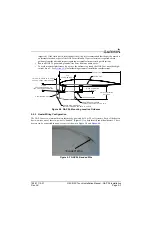
This section contains general information as well as installation information for the GAD 29. Use this
section to mount the GAD 29 unit.
NOTE
A GAD 29 cannot be installed in a system that also includes a GSU 73. For ARINC
429 I/O, use the appropriate pins on the GSU 73 instead.
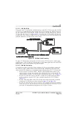
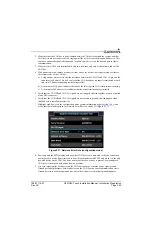
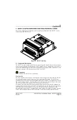
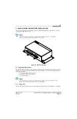
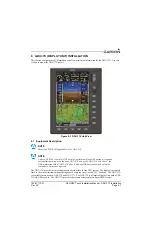
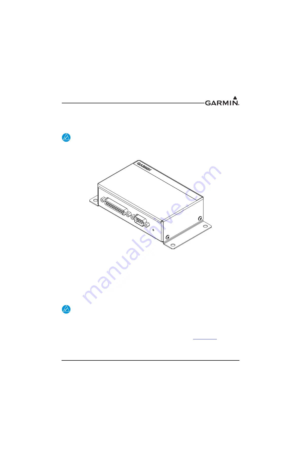
Figure 4-1 GAD 29 Unit View
4.1 Equipment Description
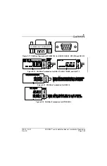
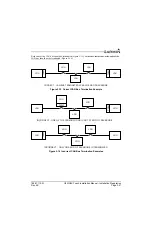
The GAD 29 allows the G3X system to interface to IFR navigators such as the GNS and GTN series. The
GAD 29 has a 25 pin D-sub connector and a 9 pin D-sub connector. These connectors will provide the
following functionality:
•
2 Low Speed ARINC 429 Transmitters
•
4 Low Speed ARINC 429 Receivers
•
1 CAN Network Port
NOTE
A GAD 29 cannot be installed in a system that also includes a GSU 73, use the GSU 73 for
ARINC 429 I/O connections in these (GSU 73) installations.
4.1.1 Status LED
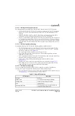
The GAD 29 has an LED on its outer case that indicates its current status. See
for details.
J291
J291
J292
J292

