
190-01115-01 G3X/G3X Touch Installation Manual - GDU 37X Config and Post Install Checkout
Rev. AC
Page 33-127
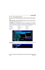
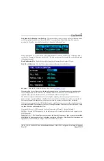
Coolant Temperature
The following sensors can be configured to monitor engine coolant temperature on the GEA 24 or GSU 73
MISC TEMP 1 inputs, or the GEA 24 MISC TEMP 1 & 2 input:
•
UMA 1B10R (or any Pt100-type RTD sensor)
•
Rotax 965531 (or any similar VDO 50-150°C thermistor sensor)
•
Rotax 966385
Rotax 912iS/915iS: For the GEA 24, select "Rotax Coolant Temp (FADEC)" for the MISC TEMP 1 input
to use coolant temperature data from the Rotax 912iS/915iS FADEC interface.
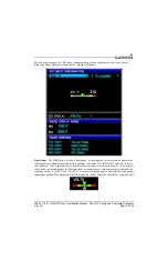
Miscellaneous Temperature
The following sensors can be configured to monitor a single miscellaneous (AUX) temperature using the
GEA 24 or GSU 73 MISC TEMP 1 inputs, or the GEA 24 MISC TEMP 2 input:
•
Thermistor (any 50-150°C thermistor such as the Rotax 965531, 966385, or the VDO 320-XXX
series)
•
UMA 1B10R, UMA 1BXR-C (or any Pt100-type RTD sensor)
•
Type J or Type K thermocouple
Rotax 912iS/915iS: For the GEA 24, select "Manifold Air Temp (Rotax FADEC)" for the MISC TEMP 1
or 2 input to use manifold air temperature data from the Rotax 912iS/915iS FADEC interface.
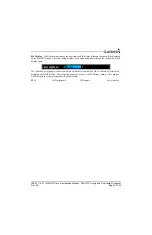
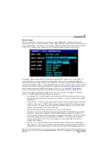
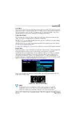
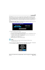
Fuel Quantity
The GEA 24 and GSU 73 support fuel quantity inputs from both analog (resistance or voltage) and digital
(frequency) sensors. "Float" type resistive fuel quantity sensors are analog devices. Capacitive fuel
quantity sensors may be analog or digital devices, depending on whether they output a voltage (analog) or
a frequency (digital).
The GEA 24 supports four fuel quantity inputs (FUEL 1 through 4), any of which can be used with an
analog or digital fuel quantity sensor.
The GSU 73 supports four analog fuel quantity inputs (FUEL 1 through 4) and two digital fuel quantity
inputs (CAP FUEL 1 and 2). Of these inputs, up four can be configured at any one time.
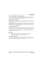
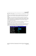
For both the GEA 24 and GSU 73, up to four fuel quantity measurements may be configured, using one
item from each of the following groups:
•
Group 1 - Fuel Quantity 1, Main Fuel 1
•
Group 2 - Fuel Quantity 2, Main Fuel 2
•
Group 3 - Aux Fuel 1
•
Group 4 - Aux Fuel 2
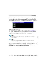
Analog and digital fuel quantity inputs may be configured interchangeably for the above listed Groups 1-4.
The "Fuel Quantity" and "Main Fuel" configurations are functionally the same, only the displayed text
differs.
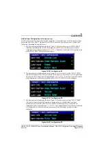
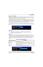
NOTE
The GSU 73 FUEL 3 and 4 analog inputs require an external pull-up resistor when used
with a resistive analog fuel quantity sensor (see
).
The analog and digital fuel quantity inputs require calibration (see


