


190-01115-01
G3X/G3X Touch Installation Manual - GSU 25/25B Installation
Rev. AC
Page 18-4
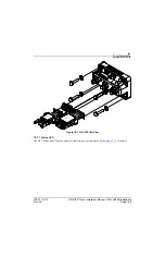
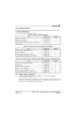
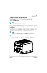
18.4 Unit Installation
Fabrication of a wiring harness is required. Sound mechanical and electrical methods and practices should
be used for installation of the GSU 25. Refer to
for wiring considerations, and to
for pinouts.
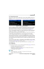
The GSU 25 connects to other LRUs in the G3X system using the CAN bus. To provide an optional
redundant path for attitude and air data, a secondary RS-232 connection to a single GDU display (typically
PFD1) is also supported. See
for wiring and configuration information.
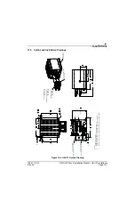
Connector kits include backshell assemblies. Garmin’s backshell connectors give the installer the ability
to quickly and easily terminate shield grounds at the backshell housing. The instructions needed to install
the jackscrew backshell are located in
NOTE
Connection to a GMU magnetometer and GTP 59 is required for ADAHRS 1 but optional
for ADAHRS 2 & 3.
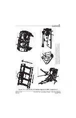
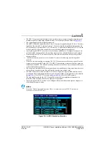
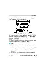
18.4.1 Mounting/Calibration Overview
It is critical that the GSU 25 is mounted in alignment with the centerline of the aircraft. The GSU 25 must
be mounted with the connectors aligned within 1.0 degree of either the longitudinal or lateral axis of the
aircraft. (see Section 18.4.1 for complete requirements)
The specification for mounting the GSU 25 such that it is level with respect to pitch/roll of the aircraft is
not nearly as restrictive, and must only be within 30.0 degrees in each axis. In most installations, the
GSU 25 is mounted relatively level with respect to the zero waterlines of the aircraft (e.g. longerons), even
though it is not required (again, must only be within 30.0 degrees). (see Section 18.4.2 for complete
requirements
Calibrating the pitch/roll offsets is also a crucial part of the installation (see
calibration, while on the ground, the aircraft must be level in both pitch/roll such that it accurately
represents the in-cruise attitude of the aircraft. This part of the calibration determines that the displayed
measured attitude of the GSU 25 is zero degrees in pitch/roll when the aircraft is in level, coordinated
cruise flight. (Note that the PFD /- 5 degrees of pitch offset adjustment in flight. This allows the
pilot to adjust the pitch offset while in flight to show a correct attitude indication on the PFD, even if the
pitch attitude was slightly off when the on the ground pitch/roll offset calibration was performed.)
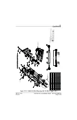
18.4.2 Mounting Requirements
The GSU 25 includes an extremely sensitive strap-down inertial measurement unit, consider the following
when selecting a mounting location:
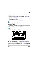
•
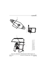
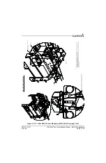
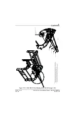
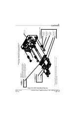
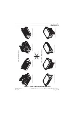
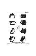
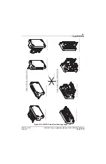
The GSU 25 can be oriented remotely in any of 24 orientations (
), but
must satisfy the mounting alignment requirements along the longitudinal/lateral axes of the
aircraft. The unit can be mounted in any of the 4 cardinal directions with the connectors pointing
up or down can also be mounted on a vertical surface, with the connectors facing up, down,
forward, aft, left, or right.
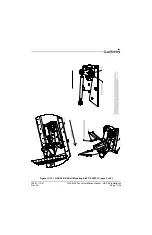
•
Although mounting the GSU 25 to the threaded holes on the back of the GDU 4XX display is not
generally recommended due to instrument panel flexing, the “Tubes Forward/Connectors Down”
configuration should be selected when this location is used.
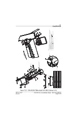
•
Mount the GSU 25 with the connectors aligned within 1.0 degree of either the longitudinal or
lateral axis of the aircraft. The direction of the unit will be accounted for during the calibration
procedure as shown in
.


