


5-12
5.1.7.2 Disconnection
detection time (H38)
If communication from the master (PLC, PC) during RS-485 linked operation (S06: operation
command FWD, REV) exceeds the specified time, an RS-485 communication error (
er5
) is
immediately generated. When performing non-fixed cycle communications, disable this function
(setting: "0"). When performing fixed cycle communications, set H38 to a longer time than the cycle
time before using the disconnection detection function.
5.1.7.3 Character
timeouts
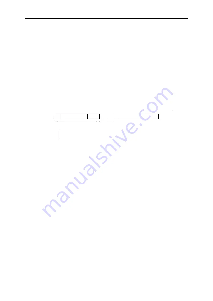
The receiving interval of transmissions is monitored with a fixed timer. If the character interval of
the data sent from the master exceeds the timer time, this function determines that the operation is
not fixed or that there has been a disconnection. The function operates with a
fixed timer of 20 ms
based on the slowest communication speed of 2400 bps, allowing for a character interval of 5 ms to
4.6 ms (12-11 bit/2400). Be aware that, if the character interval exceeds this time, communications
on the inverter side will be reset.
5.1.7.4
Timeouts on the master side
Specify the time allowed before determining that the master side (PLC, PC) will timeout if the
response from the inverter is interrupted. The specified time common to Fuji inverters (G, C, E, VG)
is
500 ms or more
. Always set the timout for the master device to this time or longer. The response
is normally returned within the internal process time (about 1 ms) + the interval timer time (H39
setting). Therefore, the timeout for the master device can be set to a little longer than the interval
timer time. However, the actual timeout time should be set to 500 ms or more to allow for multiple
connections to other types of devices (G/E series).
Data from master
→
To inverter
STA
PAR STP
STA
PAR STP
1 character
Character interval (within 20 ms)
STA: Standard bit
PAR: Parity
STP: Stop bit
Summary of Contents for FRENIC-VG Series
Page 1: ...For the STACK type User s Manual User s Manual Option Edition 24A7 E 0045 3 ...
Page 2: ......
Page 3: ...High Performance Vector Control Inverter User s Manual Option Edition ...
Page 155: ...6 5 SX Bus Interface Card 6 79 Chap 6 CONTROL OPTIONS Figure 6 5 5 ...
Page 156: ...6 80 Basic Connection Diagram Figure 6 5 6 ...
Page 344: ......
Page 346: ...For the STACK type User s Manual User s Manual Option Edition 24A7 E 0045 3 ...


