6-38
Table 6.2.15 lists function codes related to pulse train operation. See the control block diagrams in
Chapter 4 for more information.
Table 6.2.15
Parameter name
No.
Name Keypad
display
Setting range
Setting description
o12
Command pulse
selection
PLS REF SL
0
,
1
0: PG (PR) option
1: Internal speed command
o13
Pulse train input
format selection
PLS STATE SL
0 to 2
0: Two signals with a 90° phase difference between
the A- and B-phases
1: A-phase command pulse, B-phase command code
2: A-phase run forward pulse, B-phase run reverse
pulse
o14
Command pulse
compensation 1
PLS CORR 1
1 to 9999
o15
Command pulse
compensation 2
PLS CORR 2
1 to 9999
Allows the command pulse count ratio to be
changed.
o16 APR gain 1
APR-P-GAIN
0.1 to 999.9[times]
Position controller gain
o17 F/F gain 1
F/F GAIN
0.0 to 1.5[times]
Feed forward gain
o18
Deviation overrun
width
DEV OVER W
1 to 65535[pulse]
Allows 10 to 655,350 pulses to be set (10 x the
setting).
o19 Deviation zero width DEV XERO W
1 to 1000[pulse]
Sets 1 to 1,000 pulses.
F64 ASR1 input filter
ASR1-IN
0.000 to 5.000[s]
Sets the time constant for the primary delay filter
relative to the speed setting.
(1) Command pulse selection (o12)
Set to 0 when performing position control using pulses input to the PG (PR) option. Normally, the slave
setting is 0.
By contrast, set to 1 at the master when you wish to send the same pulse to the slave while triggering
pulse oscillation with an internal speed command and using pulse train operation for the master based on
that signal.
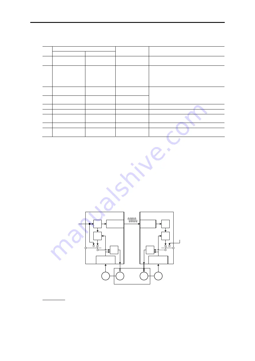
[About o12 = 1 operation]
Internal speed commands ([12] input and multi-stage speed commands, etc.) are converted into pulse
signals (oscillations), and those pulse signals are converted back into speed commands as part of position
control and enabled with [SYC]. To synchronize operation with other inverters, converted pulse signals
are output as-is and received by the PGo (PR) option.
FRENIC-VG
master
Analog [12]
Multi-stage speed
commands, etc.
Speed commands
Oscillation
circuit
Position
control
Pulse
commands
Built-in PG
outputs [FA]
and [FB]
PGo (PR)
option
Position
control
Speed
control
Speed
control
FRENIC-VG
slave
[SYC]
IM
PG
IM
PG
Synchronized
operation
Built-in PG
[PA] and [PB]
Built-in PG
[PA] and [PB]
Reception
circuit
[SYC]
Other speed
commands
Figure 6.2.31
Precautions
When internal speed commands are used to generate oscillation with a pulse train using the o12 = 1
technique, processing is performed to correct the remainder portion of each pulse. For example, when using
a 1024p/r encoder, conversion of a 1,500 r/min. command into a pulse generates 25.6 kHz pulse output
without any problem. However, a speed command of 1,000 r/min. yields a pulse of 17.06666… kHz due to
the remainder in the division operation. Remainders are corrected one by one. This correction processing
causes a slight amount of speed fluctuation, but smoothing by the speed command filter prevents it from
becoming a problem. Additionally, since synchronization accuracy is maintained by means of remainder
correction processing, the problem of missing pulses (positional shifts) does not occur.
Summary of Contents for FRENIC-VG Series
Page 1: ...For the STACK type User s Manual User s Manual Option Edition 24A7 E 0045 3 ...
Page 2: ......
Page 3: ...High Performance Vector Control Inverter User s Manual Option Edition ...
Page 155: ...6 5 SX Bus Interface Card 6 79 Chap 6 CONTROL OPTIONS Figure 6 5 5 ...
Page 156: ...6 80 Basic Connection Diagram Figure 6 5 6 ...
Page 344: ......
Page 346: ...For the STACK type User s Manual User s Manual Option Edition 24A7 E 0045 3 ...


