35
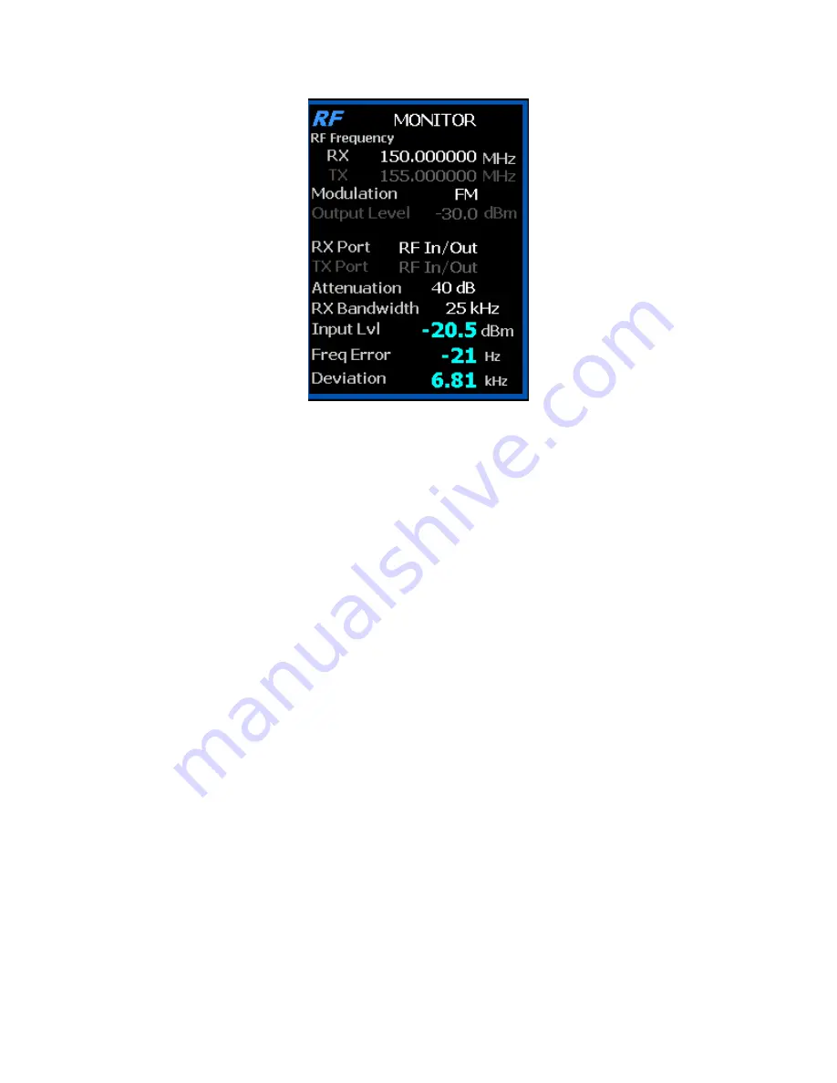
Figure 3.2.1-1
RF Zone display area showing Monitor Mode data
To enable the R8100 Monitor mode press the
Monitor
navigation button from within any menu and
confirm that “Monitor” is indicated in the lower left corner of the R8100 main display. Then press the
Esc
button repeatedly until the soft keys to the right of the display area indicate RF Zone, Audio Zone,
Display Zone, and Meter Zone. This places the R8100 at the entry point for adjusting basic Monitor mode
settings such as frequency, modulation type, etc.
Note: In Monitor mode you can bypass standard menu
navigation and jump directly to another Zone and its settings submenu with the appropriate hot key - see
paragraph 3.1.2.
Input Level
Displays the RF input level of the received carrier. Different units may be selected with the Input Level
Units setting.
Note: When the RF input power on the RF In/Out port is above +20 dBm (100 mW), the R8100 utilizes a
broadband power detector for the measurement. The “Input Lvl” field in the RF Zone changes to “Watt
Meter” to indicate this measurement mode
Watt Meter
Displays the level of broadband power applied to the RF In/Out port. Different units may be selected with
the Input Level Units setting in the RF Zone submenu.
Note: For best Watt Meter accuracy disable the Pre-amplifier in Monitor Mode, and set the Gen Port in
Generate Mode to RF In/Out.
Freq Error
Displays the frequency difference of the received carrier frequency minus the R8100 Monitor Frequency.
Summary of Contents for R8100 SERIES
Page 19: ...19 Figure 2 1 2 Left and Right Sides of the R8100...
Page 164: ...164 Figure 2 2 7 7 5 Power Profile Frame with Markers...
Page 224: ...224 Figure 3 2 9 6 1 Submenu after pressing Options soft key in the Settings menu...
Page 243: ...243 PTC Test in Monitor Mode Eye Diagram Display...
Page 244: ...244 Power Profile Display Linear and Circular Constellation Displays...
Page 245: ...245 Symbol Distribution Plot...


