239
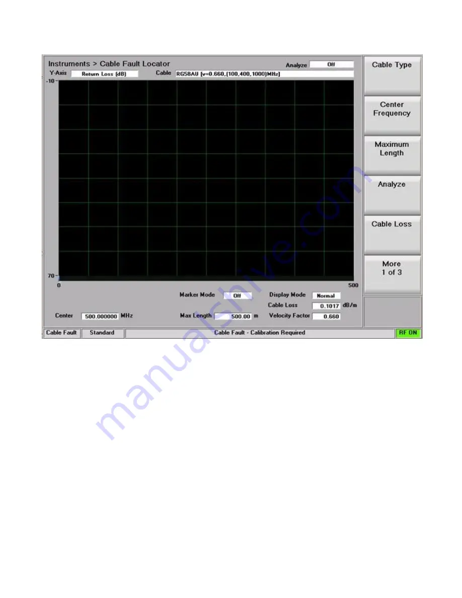
Figure 5.3.1-1
Cable Fault Instrument Display
Enter the Center Frequency, Maximum Length, Cable Loss, and Velocity Factor for the cable under test.
Note: For frequent tests or multiple frequencies it’s advantageous to save these parameters using the “Add
Cable Type” soft key function. This allows custom parameter entry for a user defined cable not on the
standard selection list. A submenu allows entering a “Cable Description” and associated cable
specifications, including attenuation factors for 3 separate frequencies. “Next” advances the menu to each
successive Frequency/Nominal Attenuation entry, and “Back” returns to the previous entry menu. Once
the 3rd frequency point is populated with data, “Save New Cable” stores the entry in R8100 memory. The
user defined cable will now appear in the “Cable Type” selection window.
Connect the Power Splitter to the R8100 as shown in Figure 5.3-1, but leave the Cable Under Test
disconnected.
Note: The Power Splitter has a symmetrical internal configuration, so connections from the R8100 and
cable under test can be made to any port on the Power Splitter (in other words all Power Splitter ports
are interchangeable). However it may be physically convenient to connect them as follows: R8100 RF
Gen Out to Power Splitter port 1; R8100 Antenna to Power Splitter port 2; Cable under test to Power
Splitter port S.
Summary of Contents for R8100 SERIES
Page 19: ...19 Figure 2 1 2 Left and Right Sides of the R8100...
Page 164: ...164 Figure 2 2 7 7 5 Power Profile Frame with Markers...
Page 224: ...224 Figure 3 2 9 6 1 Submenu after pressing Options soft key in the Settings menu...
Page 243: ...243 PTC Test in Monitor Mode Eye Diagram Display...
Page 244: ...244 Power Profile Display Linear and Circular Constellation Displays...
Page 245: ...245 Symbol Distribution Plot...


