Hardware configuration.
CNC 8070
5.
CENTRAL
UNIT + MONITO
R (ETX PLATFORM).
Conn
ecti
ons.
·92·
(R
EF
: 1911)
5.12.8 Mechatrolink bus.
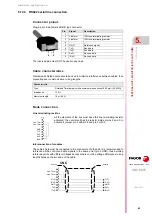
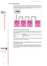
The Mechatrolink bus may be used to communicate with servos (axis and spindle) and
inverters (spindle) in Mlink-I (17 bytes) mode and Mlink-II (17 or 32 bytes) mode. With this
type of bus, up to 14 slaves may be connected in Mlink-I mode and 30 slaves in Mlink-II mode
(a repeater must be used to connect more than 16 slaves).
Mechatrolink cable characteristics.
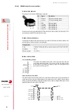
Use a specific Mechatrolink cable. The maximum length of the cable is 50 m (164 ft). The
minimum length of the cable between elements is 0.3m (1 ft) in Mlink-I mode and 0.5 m (1.7
ft) in Mlink-II mode.
Twisted-pair shielded cable should be used to minimize interference between cables, thus
preventing poor communication in long lengths.
Identification of the first and last elements of the bus. Line
terminating resistor.
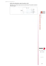
In the bus, it is necessary to use a line terminating resistor to identify which are the elements
that occupy the ends of the bus; i.e. the first and last physical element in the connection. For
the central unit, the terminating resistor is factory installed because the CNC is always at
one end of the bus.
Item.
Description.
Type.
Shielded. Twisted pair.
Impedance.
130
.
Servo
Inverter
1
2
3
n
CNC
Servo
Inverter
Servo
Inverter
Servo
Inverter
Summary of Contents for CNC 8070
Page 1: ...Ref 1911 8070 CNC Hardware configuration...
Page 8: ...BLANK PAGE 8...
Page 14: ...BLANK PAGE 14...
Page 18: ...BLANK PAGE 18...
Page 22: ...BLANK PAGE 22...
Page 24: ...BLANK PAGE 24...
Page 26: ...BLANK PAGE 26...
Page 28: ...Hardware configuration CNC 8070 1 PREVIOUS INFORMATION 28 REF 1911...
Page 94: ...Hardware configuration CNC 8070 6 CENTRAL UNIT MONITOR Q7 A PLATFORM 94 REF 1911 C70 15AT...
Page 273: ...Hardware configuration CNC 8070 273 User notes REF 1911...
Page 274: ...Hardware configuration CNC 8070 274 User notes REF 1911...
Page 275: ...Hardware configuration CNC 8070 275 User notes REF 1911...

