Hardware configuration.
CNC 8070
7.
CENTRAL U
N
IT
FOR C
ABI
NET (Q7-A
PLATFORM).
Powe
r sup
ply fo
r the modu
le.
·142·
(R
EF
: 1911)
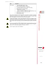
7.4
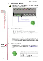
Power supply for the module.
7.4.1
Central unit electrical features.
• The unit is electrical safety class III.
• The nature of the installation where it is connected must not exceed OVC II.
• The unit must be powered with class DVC A power supply with a PELV protection output
voltage.
7.4.2
Protection against over-voltage and reverse voltage.
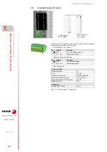
Protection against over-voltage and reverse voltage. The central unit has a F2A fuse that
may be accessed from the outside to protect against over-voltage (greater than 36 V DC or
25 V AC). The central unit is also protected against reverse connection of the power supply.
7.4.3
Voltage supply at 24 V DC.
Universal DC power supply. Use a regulated 24 V DC power supply (between -15% and
+20%) and 2 A (including voltage ripple and noise). See
Connector pinout.
Do not connect the module to a power supply that is turned on. Before connecting the module, turn
off the power supply off by unplugging the power cable.
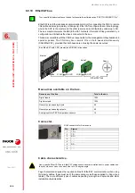
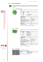
Power supply.
O v e r - v o l ta g e
protection fuse.
Plug-in part. 3-pole Phoenix-contact combicon connector (5.08 mm
pitch).
Pin
Signal.
Function.
1
- - -.
2
GND
0 V reference signal.
3
+24 V
Power supply.
Summary of Contents for CNC 8070
Page 1: ...Ref 1911 8070 CNC Hardware configuration...
Page 8: ...BLANK PAGE 8...
Page 14: ...BLANK PAGE 14...
Page 18: ...BLANK PAGE 18...
Page 22: ...BLANK PAGE 22...
Page 24: ...BLANK PAGE 24...
Page 26: ...BLANK PAGE 26...
Page 28: ...Hardware configuration CNC 8070 1 PREVIOUS INFORMATION 28 REF 1911...
Page 94: ...Hardware configuration CNC 8070 6 CENTRAL UNIT MONITOR Q7 A PLATFORM 94 REF 1911 C70 15AT...
Page 273: ...Hardware configuration CNC 8070 273 User notes REF 1911...
Page 274: ...Hardware configuration CNC 8070 274 User notes REF 1911...
Page 275: ...Hardware configuration CNC 8070 275 User notes REF 1911...

