Hardware configuration.
CNC 8070
11.
VERTICAL KEYB
/ VE
RTICAL
KEYB+MOUSE.
Bus CAN
(CAN
fag
or/CANope
n protocols).
·226·
(R
EF
: 1911)
11.7
Bus CAN (CANfagor/CANopen protocols).
CANfagor and CANopen are network communication protocols based on the CAN bus, for
connecting the CNC with remote modules and keyboards. The CAN connection supports
up to 32 devices (nodes), including the central unit; more one than keyboard and several
groups of remote modules are possible.
CAN connector.
The cable shield must be connected to the connector at both ends. The connector has two
shield pins. Both pins are equivalent and the CAN shield may be connected to either one.
CAN cable characteristics.
Use a specific CAN cable. The ends of all the wires and the shield must be protected by the
corresponding terminal (pin). Also use the terminals (pins) to secure the cable to the
connector.
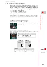
Module interconnection.
Respect the cable's minimum bending radius when connecting it. They must be connected
in series; on elements having two CAN connectors, either one may be used. Once the
elements have been connected, define their logic order in the bus and the transmission
speed.
General characteristics.
Type.
Shielded. Twisted pair (1 x 2 x 0.22 mm²).
Flexibility.
Extremely flexible. Minimum bending radius, static = 50 mm and
dynamic = 95 mm.
Cover.
PUR
Impedance.
Cat.5 (100
- 120
)
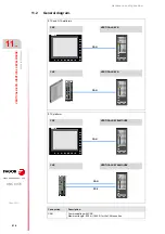
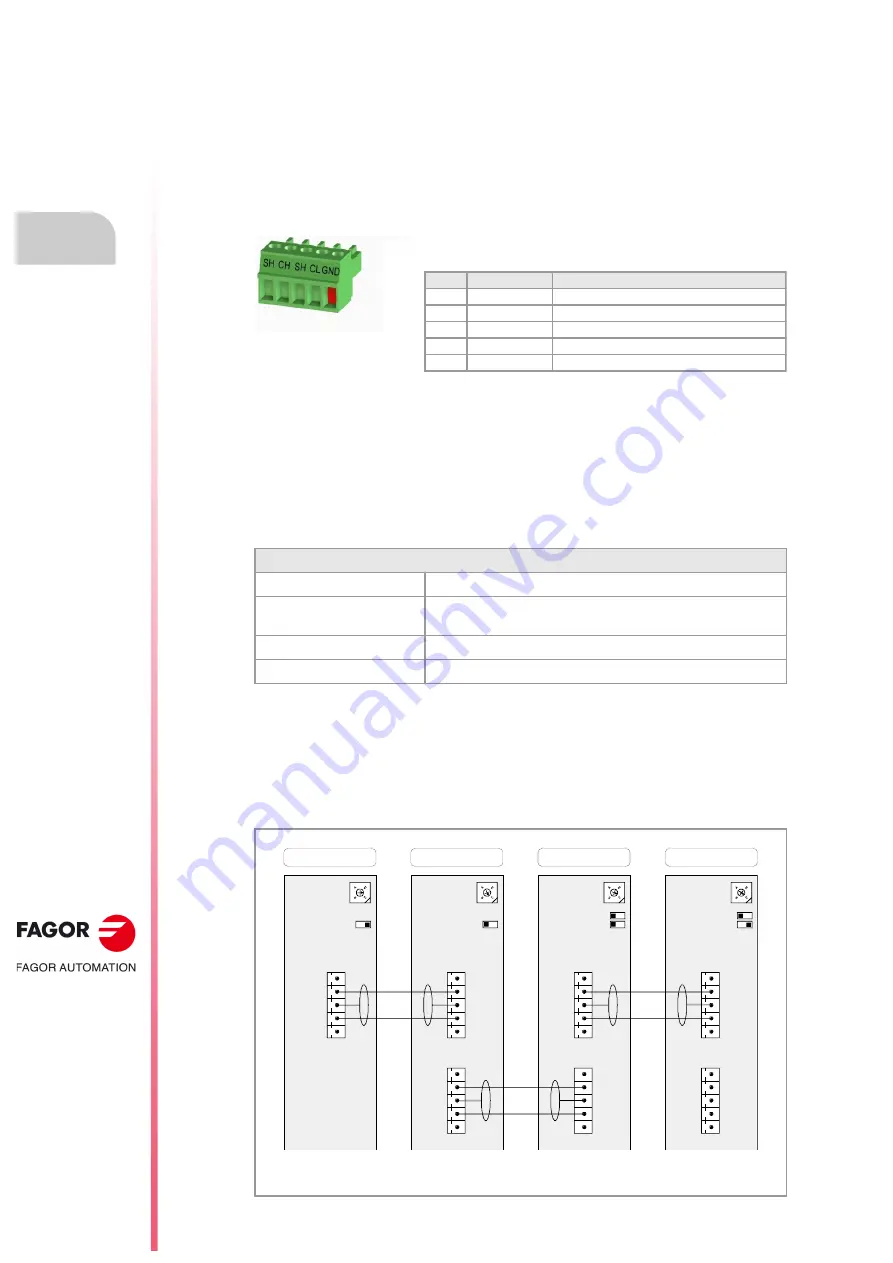
The drawing shows the CAN connection between the CPU (central unit), the operator panel and 2
groups of RIOR or RIO5 series remote modules.
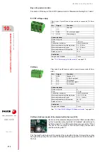
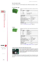
Plug-in part. 5-pole Phoenix-contact minicombicon connector (3.5 mm
pitch).
Pin.
Signal.
Function.
1
GND
Ground / 0 V.
2
CL
(LOW) bus signal.
3
SH
CAN shield.
4
CH
(HIGH) bus signal.
5
SH
CAN shield.
4
0
F
D
C
B
9
8
7
5
3
1
1
JOG PANEL
X2
ADDRESS = 3
Line Term = 0
ISO GND
CAN L
SHIELD
CAN H
SHIELD
ISO GND
CAN L
SHIELD
CAN H
SHIELD
4
0
F
D
C
B
9
8
7
5
3
1
1
MODULE 1
0
ADDRESS = 1
Line Term = 0
CNC
ISO GND
CAN L
SHIELD
CAN H
SHIELD
4
0
F
D
C
B
9
8
7
5
3
1
1
MODULE 2
0
ADDRESS = 2
ISO GND
CAN L
SHIELD
CAN H
SHIELD
Line Term = 1
1
0
Line Term = 1
4
0
F
D
C
B
9
8
7
5
3
1
ADDRESS = 0
ISO GND
CAN L
SHIELD
CAN H
SHIELD
ISO GND
CAN L
SHIELD
CAN H
SHIELD
ISO GND
CAN L
SHIELD
CAN H
SHIELD
ADD MSB = 0
ADD MSB = 0
X3
X2
X3
X2
X3
0
Summary of Contents for CNC 8070
Page 1: ...Ref 1911 8070 CNC Hardware configuration...
Page 8: ...BLANK PAGE 8...
Page 14: ...BLANK PAGE 14...
Page 18: ...BLANK PAGE 18...
Page 22: ...BLANK PAGE 22...
Page 24: ...BLANK PAGE 24...
Page 26: ...BLANK PAGE 26...
Page 28: ...Hardware configuration CNC 8070 1 PREVIOUS INFORMATION 28 REF 1911...
Page 94: ...Hardware configuration CNC 8070 6 CENTRAL UNIT MONITOR Q7 A PLATFORM 94 REF 1911 C70 15AT...
Page 273: ...Hardware configuration CNC 8070 273 User notes REF 1911...
Page 274: ...Hardware configuration CNC 8070 274 User notes REF 1911...
Page 275: ...Hardware configuration CNC 8070 275 User notes REF 1911...

