Hardware configuration.
CNC 8070
MONITOR-21 MULTITOUCH.
9.
Cab
le chara
cteri
stics.
·197·
(R
EF
: 1911)
9.8
Cable characteristics.
9.8.1
VGA video signal.
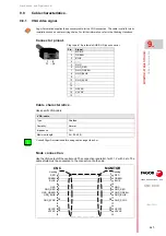
Connector pinout.
Cable characteristics.
Use specific VGA cable.
Node connection.
Use the VGA output of the central unit. The connection is parallel, 1 with 1, 2 with 2, etc. The
cable shield must be connected to the connector at both ends.
Fagor Automation supplies the necessary cable for the VGA connection. The cable is valid for static
installations such as cable carrying chains. For further information, refer to the Ordering Handbook.
·VGA· cable.
Type.
Shielded.
Flexibility.
Normal.
Impedance.
75
.
Maximum length.
5 m (16.40 ft).
Plug-in part 15-pin female SUB-D HD type connector.
Pin.
Signal.
1
MAINS
2
GREEN
3
BLUE
4
- - -
5
GND
6
GND_RED
7
GND_GREEN
8
GND_BLUE
9
- - -
10
GND_SYNC
11
- - -
12
- - -
13
HSYNC
14
VSYNC
15
- - -
1 ... 5
11 ... 15
Consult Fagor Automation before using cables longer than 5 m.
i
GND
BLUE
GREEN
GND_SYNC
GND_BLUE
GND_GREEN
GND_RED
Housing
Housing
1
CNC
MONITOR
RED
HSYNC
VSYNC
GND
BLUE
GREEN
GND_SYNC
GND_BLUE
GND_GREEN
GND_RED
RED
HSYNC
VSYNC
2
3
5
6
7
8
10
13
14
1
2
3
5
6
7
8
10
13
14
Summary of Contents for CNC 8070
Page 1: ...Ref 1911 8070 CNC Hardware configuration...
Page 8: ...BLANK PAGE 8...
Page 14: ...BLANK PAGE 14...
Page 18: ...BLANK PAGE 18...
Page 22: ...BLANK PAGE 22...
Page 24: ...BLANK PAGE 24...
Page 26: ...BLANK PAGE 26...
Page 28: ...Hardware configuration CNC 8070 1 PREVIOUS INFORMATION 28 REF 1911...
Page 94: ...Hardware configuration CNC 8070 6 CENTRAL UNIT MONITOR Q7 A PLATFORM 94 REF 1911 C70 15AT...
Page 273: ...Hardware configuration CNC 8070 273 User notes REF 1911...
Page 274: ...Hardware configuration CNC 8070 274 User notes REF 1911...
Page 275: ...Hardware configuration CNC 8070 275 User notes REF 1911...


