Hardware configuration.
CNC 8070
INSTALLING A SEN
S
OR FOR GA
P
CONTROL (LASER MODEL).
18.
·271·
(R
EF
: 1911)
18
INSTALLING A SENSOR FOR GAP CONTROL (LASER
MODEL).
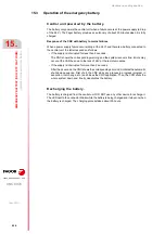
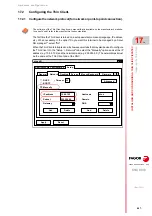
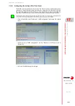
The analog input for the sensor can be installed in remote CAN modules or on the Sercos
drive of any axis. Fagor Automation recommends using a drive input. Use the machine
parameters GAPANAINTYPE and GAPANAINID to define the CNC where the sensor input
is located.
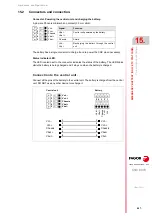
Electrical diagram.
Connecting the sensor to an analog input of the Sercos drive.
The example uses the first analog input of the drive (pins ·4· and ·5·); to use the second input,
use pins ·2· and ·3.
Connecting a sensor to an analog input on remote modules.
The analog inputs are available on modules RIO5 and RIOR.
The analog inputs of the drive are a hardware option; to access them, the drive must have a
communications interface with the analog inputs A1 or SI.
X7
AI1+
AI1-
5
4
ANALOG INPUT -
ANALOG INPUT +
DRIVE
GAP SENSOR
CNC
SERCOS
I48
AI1+
AI1-
11
9
ANALOG INPUT -
ANALOG INPUT +
RIOR
GAP SENSOR
CNC
CAN
Summary of Contents for CNC 8070
Page 1: ...Ref 1911 8070 CNC Hardware configuration...
Page 8: ...BLANK PAGE 8...
Page 14: ...BLANK PAGE 14...
Page 18: ...BLANK PAGE 18...
Page 22: ...BLANK PAGE 22...
Page 24: ...BLANK PAGE 24...
Page 26: ...BLANK PAGE 26...
Page 28: ...Hardware configuration CNC 8070 1 PREVIOUS INFORMATION 28 REF 1911...
Page 94: ...Hardware configuration CNC 8070 6 CENTRAL UNIT MONITOR Q7 A PLATFORM 94 REF 1911 C70 15AT...
Page 273: ...Hardware configuration CNC 8070 273 User notes REF 1911...
Page 274: ...Hardware configuration CNC 8070 274 User notes REF 1911...
Page 275: ...Hardware configuration CNC 8070 275 User notes REF 1911...

