


Hardware configuration.
CNC 8070
6.
CEN
T
RAL UNIT + MONITOR (Q7-A
PLATFORM).
Conn
ecti
ons.
·118·
(R
EF
: 1911)
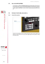
6.8
Connections.
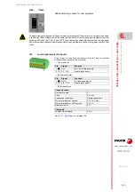
6.8.1
Ground connection.
Connect the CNC ground terminal to the main ground terminal so that the EMC performs
properly. Before connecting the inputs and outputs, make sure that the ground connection
has been made.
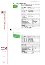
6.8.2
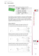
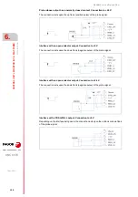
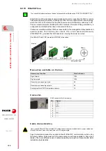
Connecting the relay for the emergency chain.
Single-contact relay, normally open contact that closes when the CNC is powered up and
running properly; it opens again when the CNC is turned off or when an internal failure occurs.
The relay withstands up to 1 A at 24 V.
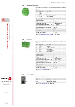
Connector pinout.
Plug-in part. 2-pole Phoenix-contact minicombicon connector (3.5 mm pitch).
Do not handle the connectors while the CNC is turned on (inputs/outputs, feedback, etc.). Make sure
that the device is not powered before handling the connectors.
Do not make any connections while the CNC is powered. Disconnect the power before making a
connection.
It is up to the system integrator to meet all the requirements of local and national electrical codes as
well as all the regulations applicable regarding the grounding of the whole unit.
Ground.
Pin.
Signal.
Function.
1
RELAY
Relay for the emergency chain.
2
RELAY
Relay for the emergency chain.
Summary of Contents for CNC 8070
Page 1: ...Ref 1911 8070 CNC Hardware configuration...
Page 8: ...BLANK PAGE 8...
Page 14: ...BLANK PAGE 14...
Page 18: ...BLANK PAGE 18...
Page 22: ...BLANK PAGE 22...
Page 24: ...BLANK PAGE 24...
Page 26: ...BLANK PAGE 26...
Page 28: ...Hardware configuration CNC 8070 1 PREVIOUS INFORMATION 28 REF 1911...
Page 94: ...Hardware configuration CNC 8070 6 CENTRAL UNIT MONITOR Q7 A PLATFORM 94 REF 1911 C70 15AT...
Page 273: ...Hardware configuration CNC 8070 273 User notes REF 1911...
Page 274: ...Hardware configuration CNC 8070 274 User notes REF 1911...
Page 275: ...Hardware configuration CNC 8070 275 User notes REF 1911...