Hardware configuration.
CNC 8070
7.
CENTRAL U
N
IT
FOR C
ABI
NET (Q7-A
PLATFORM).
Conn
ecti
ons.
·160·
(R
EF
: 1911)
7.8.3
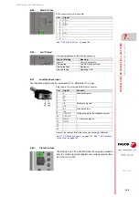
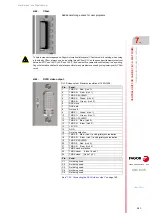
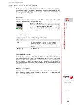
Connecting the DVI-D video output.
Digital video output, with a maximum resolution of 1920×1200.
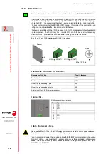
Characteristics of the DVI-D cable.
7.8.4
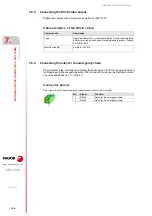
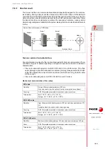
Connecting the relay for the emergency chain.
Single-contact relay, normally open contact that closes when the CNC is powered up and
running properly; it opens again when the CNC is turned off or when an internal failure occurs.
The relay withstands up to 1 A at 24 V.
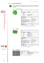
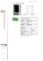
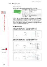
Connector pinout.
Plug-in part. 2-pole Phoenix-contact minicombicon connector (3.5 mm pitch).
Characteristic.
Description.
Type.
Single link cable (18+1) or dual link cable (24+1) with triple shielding
and ferrite cores on both ends. Recommended reference; Digitus
AK-320101-050.
Maximum length.
5 meters (16.40 ft).
Pin.
Signal.
Function.
1
RELAY
Relay for the emergency chain.
2
RELAY
Relay for the emergency chain.
Summary of Contents for CNC 8070
Page 1: ...Ref 1911 8070 CNC Hardware configuration...
Page 8: ...BLANK PAGE 8...
Page 14: ...BLANK PAGE 14...
Page 18: ...BLANK PAGE 18...
Page 22: ...BLANK PAGE 22...
Page 24: ...BLANK PAGE 24...
Page 26: ...BLANK PAGE 26...
Page 28: ...Hardware configuration CNC 8070 1 PREVIOUS INFORMATION 28 REF 1911...
Page 94: ...Hardware configuration CNC 8070 6 CENTRAL UNIT MONITOR Q7 A PLATFORM 94 REF 1911 C70 15AT...
Page 273: ...Hardware configuration CNC 8070 273 User notes REF 1911...
Page 274: ...Hardware configuration CNC 8070 274 User notes REF 1911...
Page 275: ...Hardware configuration CNC 8070 275 User notes REF 1911...

