Service Manual_AVA1_ENG-20220922_I
17
Initial Operation of Ink Ribbon and Transfer Film
Overview
Control description
The RFID PCB makes initial communication with Main board and ID-key to acquire the type and
remaining amount information of ink ribbon. When ink ribbon is used by initial operation, the remaining
amount information of ink ribbon is updated.
Take-up operation of the Ink Ribbon and Transfer Film is performed to detect the remaining amount and
type of ribbon.
If an error such as undetected clock of the ribbon spool is detected during the take-up operation, the
operation is stopped, and error information is displayed on the operation panel to prompt the operator
to check the status of the ribbon.
In addition, if the end of the ribbon is detected, the operation is stopped, and error information is
displayed on the operation panel to prompt the operator to replace the ribbon.
By setting [Initialize Mode], it is possible to omit the above operation during initialization. When
omitted, the above operation is performed when printing for the first time.
If the ribbon type is changed after this initialization operation, the initialization operation will be
performed in response to the next print request.
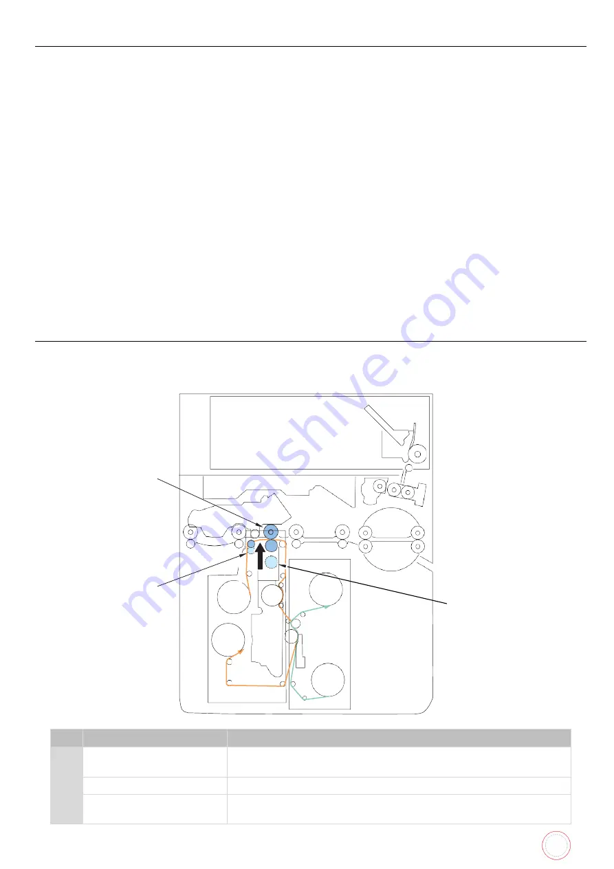
Secondary Transfer Assembly
Overview
Transferring the image from the Transfer Film to the card.
No. Name
Function
[1]
Heat Roller
Retransfers the image primarily transferred to the film onto to
the card.
[2]
Peeling Shaft
Peels the film from the card after the secondary transfer.
[3]
Card Feed Roller 3
Presses the card against the Heat Roller during the secondary
transfer.
[3]
[2]
[1]
Summary of Contents for AV1H0000BD
Page 1: ...Service Manual_AVA1_ENG 20220922_I 1 AVANSIA SERVICE MANUAL...
Page 73: ...Service Manual_AVA1_ENG 20220922_I 73 Drawing 9 HEAT ROLLER CP011845 HEAT ROLLER MODULE S10248...
Page 74: ...Service Manual_AVA1_ENG 20220922_I 74 Drawing 10 DECURL MODULE CP011976 DECURL SPRING CP011978...
Page 76: ...Service Manual_AVA1_ENG 20220922_I 76 Drawing 12 PACKAGING BOX AND FOAM S10205...
Page 109: ...Service Manual_AVA1_ENG 20220922_I 109 Tools required...
Page 118: ...Service Manual_AVA1_ENG 20220922_I 118 6 Move the hinge outwards 7 Remove the two screws...
Page 133: ...Service Manual_AVA1_ENG 20220922_I 133 8 Unplug the two sensors 9 Remove the three screws...
Page 135: ...Service Manual_AVA1_ENG 20220922_I 135 12 Remove the heat roller horizontally...
Page 139: ...Service Manual_AVA1_ENG 20220922_I 139 6 Remove the V ring 7 Remove the axis...
Page 158: ...Service Manual_AVA1_ENG 20220922_I 158 7 Remove the two screws...
Page 167: ...Service Manual_AVA1_ENG 20220922_I 167 13 Unplug these cables 14 Open the cables holder...
Page 221: ...Service Manual_AVA1_ENG 20220922_I 221 8 Close the front cover...
Page 275: ...Service Manual_AVA1_ENG 20220922_I 275 Printer details Ribbon details...
Page 286: ...Service Manual_AVA1_ENG 20220922_I 286 BLOCK PLAN FOR ELECTRIC PARTS...
Page 287: ...Service Manual_AVA1_ENG 20220922_I 287...
Page 288: ...Service Manual_AVA1_ENG 20220922_I 288...
Page 289: ...Service Manual_AVA1_ENG 20220922_I 289...
Page 290: ...Service Manual_AVA1_ENG 20220922_I 290...
Page 291: ...Service Manual_AVA1_ENG 20220922_I 291 MAIN BOARD PLAN...
Page 293: ...Service Manual_AVA1_ENG 20220922_I 293 www evolis com...


