Hub van Doorneweg 8 • 2171 KZ Sassenheim – NL •
T
+31(0)252 228850 •
F
+31(0)252 228235 •
E
I
euronormdrives.com
22
23
NEURN030000_220_A
NEURN030000_220_A
6.4 Control circuit terminals
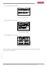
6.4.1 Control circuit terminals arrangement
1. Control panel control circuit terminals
Control panel control circuit terminals
6.4.2 Description of control circuit terminals
Category
Symbol
Name
Function
Power supply
+10V-GND
+10V power
supply
10V power supply, maximum output current: 10mA
Generally it is used as power supply of external potentiometer, potentiometer resistance range:
1~5kΩ
+24V-COM
+24V power
supply
24V power supply, generally it is used as power supply of digital input and output
terminals and external sensor.
Maximum output current: 200mA
PLC
External power
input terminal
The use of external signal when driving, PLC to be connected with an external power supply,
please unplug the PLC jumper. Factory default and +24V connection..
Analog input
AI1-GND
Analog input
terminal 1
1. Input range:(DC 0~10V/0~20mA), depends on the selected AI1 jumper on control panel.
2. Input impedance: 20kΩ with voltage input, 500Ω with current input.
AI2-GND
Analog input
terminal 2
1. Input range:(DC 0~10V/0to 20mA), depends on the selected AI2 jumper on control panel.
2. Input impedance: 20kΩ with voltage input, 500Ω with current input.
AI3
Analog input
terminal 3
1. Input range:DC-10~+10V
2. Voltage input impedance:20kΩ;
3. AI3 reference potential can be GND or -10V.


