Creating Network Maps
6-26
Customizing Your Map
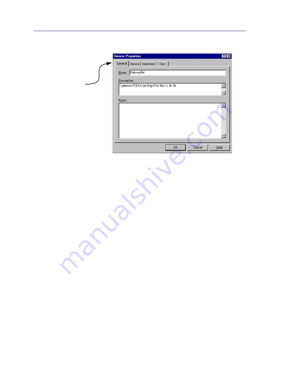
Figure 6-19. The Device Properties Window
By default, device icons will be labeled by the MIB-II
sysName
(if one has been assigned)
or, if no name has been assigned, by IP address. You can change the icon name via the
Device Properties window; for more detailed, see
Editing Device Properties
in Chapter
4,
List Views
.
Customizing Your Map
In addition to the manageable nodes described in the sections above, your maps can also
contain a variety of non-manageable graphical objects that can help you create a better
visual display of your network configuration. Alignment and layering tools are also
provided that allow you to organize and align map objects with the click of a mouse
button. Drawing, layering, and alignment tools are available either from the toolbar (see
Figure 6-20
) or from the
Draw
and
Layout
menus on the primary window menu bar.
Click on the tabs
to display the four
different pages
available in the
Device Properties
window.
Summary of Contents for Netsight
Page 1: ...User s Guide...
Page 2: ......
Page 12: ...Contents xii...
Page 52: ...Overview of NetSight Element Manager 2 36 Backing Up Data Files...
Page 82: ...Discovering Nodes 3 30 Using the Subnets Window...
Page 130: ...List Views 4 48 List Views and Maps...
Page 148: ...Tree Views 5 18 Tree Views and Maps...
Page 212: ...Creating Network Maps 6 64 Managing Maps and Folders...
Page 220: ...Node Management Overview 7 8 PING...
Page 234: ...Batch Customization via AddTool AddImage and AddDevType A 14 Viewing the Log File...


