70
ADVANCED USER GUIDE
IP66/Nema 4X variable speed drive
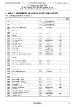
MENU 7: ASSIGNMENT OF ANALOG INPUTS AND OUTPUTS
CONTROL TECHNIQUES
3854 en - 03.2008 / b
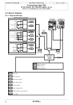
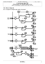
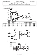
9.2 - Menu 7 diagram
9.2.1 - Assignment of analog I/O
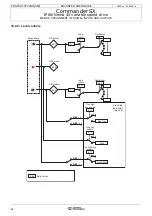
9.2.2 - Scaling block
9.2.3 - Temperature indications
Analog
or digital
input
1
Input
invert
PTC
status
A - D
10 bits
Mode
Scaling
4-.20
20-.4
dIn
20-4
4-20
20-0
v ol t
1
0
6
1
0-20
0
2
3
4
5
7
CtP
8
Destination
Destination
or Source
ADIO3
feature
X - 1
A - D
10 bits
Current
loop loss
Mode
ADI1
input level
ADI2
input level
ADIO3
input or
output level
Scaling
4-.20
20-.4
20-4
4-20
20-0
v ol t
dIn
1
0
6
1
2
0-20
0
3
4
5
7
4.20i.
20.4i.
20.4i
4.20i
20.0i
0.10i
dIn
6
1
2
0.20i
0
3
4
5
0.20o
4.20o
0.10o
10
8
9
7
Destination
X - 1
ADI1
ADI2
ADIO3
Input
invert
Analog
input or
output 3
A - D
10 bits
Current
loop loss
(input only)
Mode
Scaling
1
0
X - 1
C
T
P
3300
1800
R
I
Trip
I
N
P
U
T
O
U
T
P
U
T
Analog
or digital
input
2
Input invert
Current
loop loss
7.27
7.28
7.29
7.01
7.02
7.65
7.03
7.16
7.12
7.08
7.58
7.59
7.60
7.09
7.10
7.14
7.18
7.33
7.13
7.17
7.06
7.11
7.15
Potentiometer
Input invert
Potentiometer
input
Read
1
0
Destination
Source
X - 1
Scaling
7.67
7.69
7.63
7.64
7.68
7.62
7.61
IGBT junction temperature
Internal braking resistor temperature
7.34 7.66

