45
ADVANCED USER GUIDE
IP66/Nema 4X variable speed drive
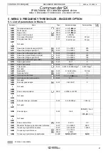
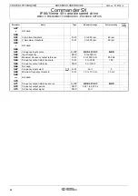
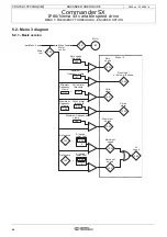
MENU 3: FREQUENCY THRESHOLDS - ENCODER OPTION
CONTROL TECHNIQUES
3854 en - 03.2008 / b
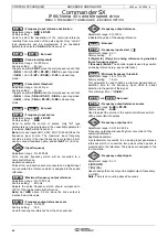
: Total inertia (
)
Adjustment range : 0.001 to 32.000 Kkgm
2
Factory setting
: 0.001 Kkgm
2
Corresponds to the total inertia applied to the motor (motor
i load inertia).
This parameter is used for automatic calculation of the gains
(see
3.17
), and to provide a torque correction during
acceleration if necessary.
: Not used
: Bandwidth (
)
Adjustment range : 0.1 to 255.0 Hz
Factory setting
: 10.0 Hz
Used to set the bandwidth taken into account with speed loop
operating mode 1 (see
3.17
).
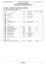
: Damping factor (
)
Adjustment range : 0 to 10.0
Factory setting
: 1.0
Used to set the damping factor taken into account with speed
loop operating mode 1 (see
3.17
).
: Hard speed reference (
)
Adjustment range : 0 to 2 x
1.06
rpm
Factory setting
: 0
This hard speed reference is an additional reference which is
not affected by the ramps.
Function not available.
: Hard speed reference selector
(
)
Adjustment range : 0 or 1
Factory setting
: 0
0 (Off) (OFF): Hard speed reference selector inactive.
1 (On) (On): Used to add an unramped speed reference to
the main reference.
Function not available.
: Not used
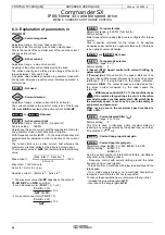
: Encoder phase angle (
)
Adjustment range : 0 to 359.9°
Factory setting
: 0
Indicates the result of the phasing test. It is stored when the
drive is powered down and will be modified automatically only
after a new phasing test.
• The phase angle, where it is known, can be
entered manually. Any incorrect value can cause
the motor to rotate in the wrong direction or trip the drive.
to
: Not used
: Drive encoder position (
)
Adjustment range : -32768 to +32767
Indicates the position of the encoder in relation to the line it
was on at power-up.
to
: Not used
: Encoder lines per revolution
Adjustment range : 0 to 32000 lpr
Factory setting
: 1024 lpr
Used to configure the number of lines per encoder revolution.
Converts the encoder input into a speed.
to
: Not used
: Encoder type
Adjustment range : 0 to 8
Factory setting
: 0 if
11.31
= 0 to 2
3 if
11.31
= 3
0 (INCREMENTAL) (Incr.) : Quadrature incremental
encoder
1 (Increm. FD) (Fd): Incremental encoder with Frequency/
Direction output
2 (Increm. FW/RV) (Fr): Incremental encoder with FWD/REV
outputs
3 (Increm. UVW) (CoMM): Incremental encoder with
commutation channels
4 (HALL EFFECT) (haLL): Hall effect sensor
5 (SENSORLESS 1) (tyP1): Sensorless mode 1
6 (SENSORLESS 2) (tyP2): Sensorless mode 2
7 (SENSORLESS 3) (tyP3): Sensorless mode 3
8 (SENSORLESS 4) (tyP4): Sensorless mode 4
to
: Not used
: Drive encoder filter (
)
Adjustment range : 0 to 10
Factory setting
: 3.0
This parameter is used to insert a sliding window filter in the
encoder speed feedback, such that:
time constant = 2
3.42
ms.
This is particularly useful for attenuating the current demand
when the load has high inertia and high gain is necessary on
the speed loop. If the filter is not enabled under these
conditions, it is possible for the speed loop output to change
continuously from one current limit to another, disabling the
integral function of the speed loop.
The filter is inactive if
3.42
= 0.
: Maximum frequency input encoder reference
Adjustment range : 0 to 32000
Factory setting
: 5000
Adjusts the input frequency which should correspond to 100%
of the destination numerical value.
: Frequency input reference scale
Adjustment range : 0 to 2.0000
Factory setting
: 1.0000
Used for scaling the numerical reference to be converted into
pulses.
: Frequency input reference
Adjustment range : 0 to 100% (
); ± 100% (
)
Indicates the value of the numerical reference resulting from
conversion of the pulse signal.
3.18
3.19
3.20
3.21
3.22
3.23
3.24
3.25
3.26
3.28
3.29
3.30
3.33
3.34
3.35
3.37
3.38
3.39
3.41
3.42
3.43
3.44
3.45

