51
ADVANCED USER GUIDE
IP66/Nema 4X variable speed drive
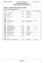
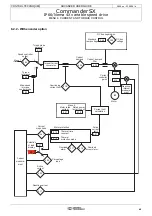
MENU 4: CURRENT AND TORQUE CONTROL
CONTROL TECHNIQUES
3854 en - 03.2008 / b
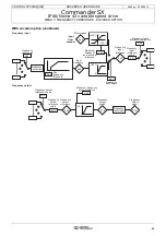
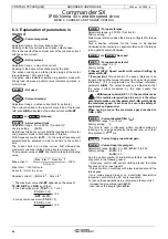
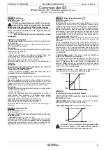
: Thermal time constant
Adjustment range : 0 to 250 s
Factory setting
: 89 s
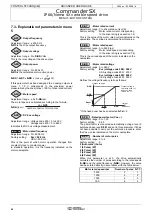
This parameter is used to define the motor thermal protection.
If known, the thermal time constant of the motor should be
entered directly in
4.15
. Otherwise it should be calculated as
a function of the maximum time for which the motor can
tolerate 150% I
N
.
4.15
=
Note: When
7.11
= 8 (ADI2 configured as a PTC input), it is
possible to deactivate the motor thermal protection (itAC
motor overload trip) by setting
4.15
= 0.
: Thermal protection mode
Adjustment range : 0 or 1
Factory setting
: 0
0 (Trip) (deF): The drive will trip when the threshold
defined in parameter
4.15
is reached.
1 (Curr. limit) (Auto): The limiting current will automatically
be reduced below 100% I
N
when the threshold defined in
parameter
4.15
is reached.
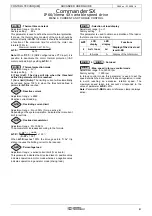
: Reactive current
Adjustment range : ± 9999
Reactive current reading.
: Overriding current limit
Adjustment range : 0 to +300% (% max. active In)
Depending on the system operation, indicates the rms current
limit in real time.
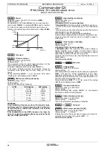
: Overload accumulator
Adjustment range : 0 to 100.0%
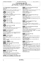
The accumulator increases according to the formula
4.19
=
When
4.19
reaches 100%, the drive goes into "It Ac" trip
state or causes the limiting current to be reduced.
: Percentage load
Adjustment range : ± active current limit (% active In)
This parameter indicates the drive load level. A positive value
indicates operation in motor mode whereas a negative value
indicates operation in generator mode (driving load).
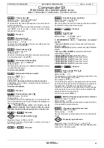
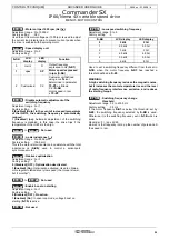
: Selection of load display
Adjustment range : 0 or 1
Factory setting
: 0
This parameter is used to obtain an indication of the load or
the total current on the display.
to
: Not used
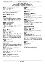
: Max. speed in torque control mode
Adjustment range : 0 to 32000 rpm
Factory setting
: 1500 rpm
In torque control mode, this parameter is used to set the
speed at which the drive reverts to speed regulation, in order
to avoid reaching an excessive rotation speed. The
maximum speed taken into account corresponds to the
value of parameter
4.52
+ 20%.
Note: Parameter
1.06
Maximum reference clamp is always
active.
4.15
Maximum duration at 150 % I
N
0.674
Maximum duration at 150 % I
N
0.674
4.16
4.17
4.18
4.19
4.01
2
(1-e
-t/
4.15
)
(
5.07
x 1,05)
2
x 100
%
4.20
4.21
LCD
display
LED
display
Functions
0
As % Inom
Ld
Display of the drive load
level
4.20
.
1
In Amps
A
Display of the total motor
4.21
4.22
4.51
4.52

