79
ADVANCED USER GUIDE
IP66/Nema 4X variable speed drive
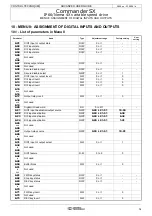
MENU 8: ASSIGNMENT OF DIGITAL INPUTS AND OUTPUTS
CONTROL TECHNIQUES
3854 en - 03.2008 / b
10.3 - Explanation of parameters in
menu 8
Note: The sampling period is 2 ms for the digital inputs and
outputs.
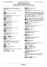
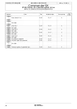
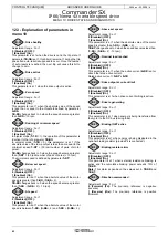
: DIO1 input or output state
Adjustment range : 0 or 1
This parameter indicates the state of the input or output.
0 (Disabled) (OFF) Inactive.
1 (Enabled) (On): Active.
: DI2 input state
Adjustment range : 0 or 1
This parameter indicates the state of the input.
0 (Disabled) (OFF) Inactive.
1 (Enabled) (On): Active.
: DI3 input state
Adjustment range : 0 or 1
This parameter indicates the state of the input.
0 (Disabled) (OFF): Inactive.
1 (Enabled) (On): Active.
: DI4 input state
Adjustment range : 0 or 1
This parameter indicates the state of the input.
0 (Inactive) (OFF): Inactive.
1 (Active) (On): Active.
and
:Not used
: Relay output status
Adjustment range : 0 or 1
This parameter indicates the state of the output relay.
0 (Open) (OPen): RL1O open, RL1C closed.
1 (Closed) (CloS): RL1O closed, RL1C open.
:Not used
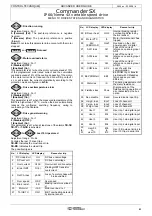
: Secure disable input
Adjustment range : 0 or 1
This parameter indicates the state of the secure disable input
(at the terminals).
0 (Disabled) (diSb): Drive disabled.
1 (Enabled) (Enab): Drive enabled.
: Secure disable select
Adjustment range : 0 or 1
Factory setting
: 1
0 (Drive enable) (Enab): The SDI input is used as a simple
locking input.
1 (Secur.disab.) (Secu): The SDI input is used as a safety
input. In order to conform to safety standard EN 954-1
category 3, the drive must be wired in accordance with
the recommended diagram in the installation and
commissioning manual ref. 3840.
Note: Modifications to
8.10
must be made with the drive
disabled.
• The secure disable input function is automatically
disabled
8.10
= 0, when the drive is controlled via
keypad, console or fieldbus, for example, when using the
"Pad" preset configuration or when
6.43
= 1 to 3.
: DIO1 input or output invert
Adjustment range : 0 or 1
Factory setting
: 0
This parameter is used to invert the digital input or output.
0 (Disabled) (OFF): Not inverted.
1 (Enabled) (On): Inverted.
: DI2 input invert
Adjustment range : 0 or 1
Factory setting
: 0
This parameter is used to invert the digital input.
0 (Disabled) (OFF): Not inverted.
1 (Enabled) (On): Inverted.
: DI3 input invert
Adjustment range : 0 or 1
Factory setting
: 0
This parameter is used to invert the digital input.
0 (Disabled) (OFF): Not inverted.
1 (Enabled) (On): Inverted.
: DI4 input invert
Adjustment range : 0 or 1
Factory setting
: 0
This parameter is used to invert the digital input or output.
0 (Disabled) (OFF): Not inverted.
1 (Enabled) (On): Inverted.
and
:Not used
: Output relay invert
Adjustment range : 0 or 1
Factory setting
: 0
This parameter is used to invert the relay status.
0 (Disabled) (OFF): Not inverted.
1 (Enabled) (On): Inverted.
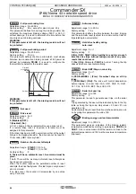
WARNING:
When the secure disable function is enabled
8.10
= 1
(sEcu), the value of
8.17
is fixed at 0, and cannot be
modified.
and
:Not used
8.01
8.02
8.03
8.04
8.05
8.06
8.07
8.08
8.09
8.10
8.11
8.12
8.13
8.14
8.15
8.16
8.17
8.18
8.19

