81
ADVANCED USER GUIDE
IP66/Nema 4X variable speed drive
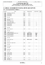
MENU 8: ASSIGNMENT OF DIGITAL INPUTS AND OUTPUTS
CONTROL TECHNIQUES
3854 en - 03.2008 / b
to
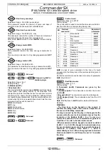
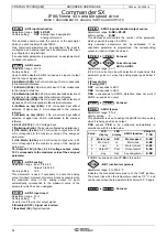
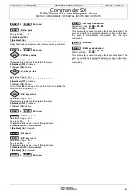
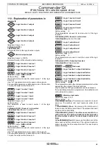
: Not used
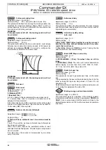
: Buffer block
Adjustment range : 0 or 1
Factory setting
: 0
0 (Disabled) (OFF)
1 (Enabled) (On)
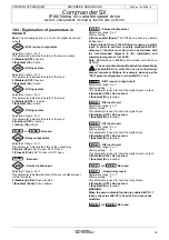
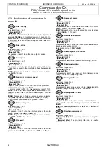
This parameter is used to make a link directly between a
binary destination parameter and a binary source parameter.
to
: Not used
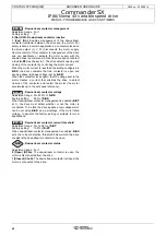
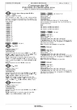
: FWD key status
Adjustment range : 0 or 1
This parameter indicates the state of the input.
0 (Inactive) (OFF): Inactive.
1 (Active) (On): Active.
: Stop key status
Adjustment range : 0 or 1
This parameter indicates the state of the input.
0 (Inactive) (OFF): Inactive.
1 (Active) (On): Active.
To use this state and assign it to another function, disable the
Stop function using
6.12
= 0.
: REV key status
Adjustment range : 0 or 1
This parameter indicates the state of the input.
0 (Inactive) (OFF): Inactive.
1 (Active) (On): Active.
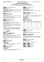
to
: Not used
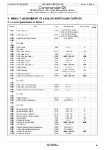
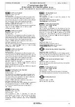
: FWD key invert
Adjustment range : 0 or 1
Factory setting
: 0
This parameter is used to invert the digital input.
0 (Disabled) (OFF): Not inverted.
1 (Enabled) (On): Inverted.
: Not used
: REV key invert
Adjustment range : 0 or 1
Factory setting
: 0
This parameter is used to invert the digital input.
0 (Disabled) (OFF): Not inverted.
1 (Enabled) (On): Inverted.
to
: Not used
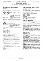
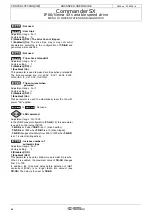
: FWD key destination
Adjustment range :
0.00
to
21.51
Factory setting
:
0.00
This parameter is used to assign the input destination. The
user can modify the input destination at any time. In this case,
the input is automatically unassigned from the logic
commands.
: Not used
: REV key destination
Adjustment range :
0.00
to
21.51
Factory setting
:
0.00
This parameter is used to assign the input destination. The
user can modify the input destination at any time. In this case,
the input is automatically unassigned from the logic
commands.
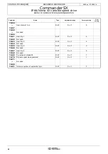
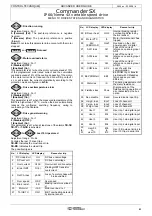
8.42
8.49
8.50
8.51
8.60
8.61
8.62
8.63
8.64
8.70
8.71
8.72
8.73
8.74
8.80
8.81
8.82
8.83

