49
Operation
User Controls
IND100064-46
OSD Menu, Navigation and Hotkeys:
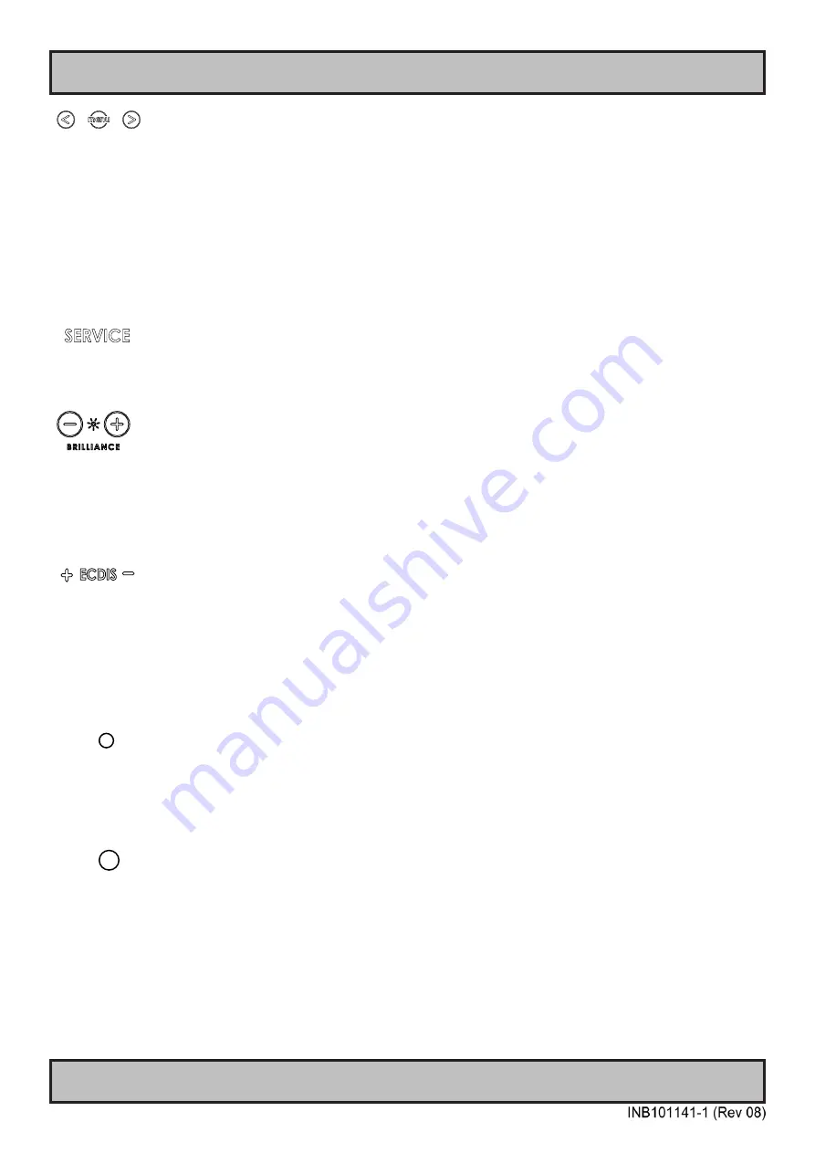
The “<” and “>” symbols have two functionalites. If the OSD (On Screen Display) menu was activated (and is clearly
visible on screen), both the “<” and “>” are used to navigate and set options within the OSD menu. If the OSD menu
is not activated (no OSD visible on screen), both the “<” and “> symbols function as hotkeys. To use the defined
hotkeys assigned, touch the “<” or “>” symbols. The hotkey functionality can be changed or disabled by accessing the
main On Screen Display (OSD) menu and the appropriate menu function. With Hotkey functionality you can define
options from the OSD menu for easier control and everyday usage of the display unit.
To access the main OSD menu, touch anywhere on the “MENU” circle symbol and the OSD menu will clearly be seen
as an overlay over the existing displayed image. The complete definition of all the menus and functions are available
in the “OSD MENU FUNCTIONS” chapter in this manual.
Action Indicators:
SERVICE
= Reserved for future use, no built-in function defined.
.
Brightness Adjust:
Brilliance / Brightness adjustment of the displayed image is adjusted by touching the (-) or (+) illuminated symbols.
The entire area of text and symbols are visible as long as the unit is powered. Note that only the (-) and (+) are touch
sensitive while the “*” and “BRILLIANCE” symbols are not. The symbols (-) and (+) are also used to change values in
the OSD menu when its activated / function selected for adjusting.
ECDIS Status / Indicator:
(optional factory standard)
For units that have been factory ECDIS calibrated the text “ECDIS” will illuminate in green constantly as long as the
unit is powered. The “+” and “-” symbols will illuminate in red when the Brightness/Brillance is adjusted either above or
below ECDIS factory calibration point.
To be able to stay within ECDIS calibrated range, please assure that both the “+” and “-” are not illuminated and that
“ECDIS” text remains illuminated during operation. Note that by touching these symbols no action will be performed or
has been assigned.
Light Sensor:
Used to sense level of ambient light in the surrounding environment. The sensor data can be read by suitable software
through the Hatteland Technology SCOM functionality of the unit and thus can be used to control brightness remotely.
Note: This sensor is barely visible to the eye and lies under the glass. It has no illumination behind to indicate it’s
position. Touching or covering this area will naturally make the sensor data inaccurate and should be avoided!
Buzzer:
Only functional for units ordered with Buzzer functionality. Frequency range is 1500-2500Hz. The location of the
buzzer hole (physical hole in glass) is barely visible to the eye. Touching this area will naturally mute buzzer sound or
in some cases make it lower or change audible frequency. In no circumstances should this area be blocked by either
stickers or objects! Please review the “Pinout Assignments” chapter in this manual for controlling the Buzzer
functionality and review the Serial Remote Control Interface (SCOM) protocol document, located at:
https://www.hattelandtechnology.com/hubfs/pdfget/inb100018-6.htm
Summary of Contents for Hatteland X Series
Page 8: ...8 This page left intentionally blank...
Page 9: ...9 General...
Page 17: ...17 Installation...
Page 35: ...35 Maintenance...
Page 47: ...47 Operation...
Page 83: ...83 Operation Advanced DDC CI...
Page 87: ...87 Specifications...
Page 98: ...98 This page left intentionally blank...
Page 99: ...99 Technical Drawings...
Page 101: ...101 IND100132 281 Technical Drawings HD 55T22 MVD MA1 TxGx Cable Openings...
Page 111: ...111 Technical Drawings Accessories...
Page 116: ...116 This page left intentionally blank...
Page 117: ...117 Appendixes...
Page 131: ...131 Appendix IND100077 24 User Notes...
Page 133: ...133 Revision History Appendix IND100077 161...
Page 134: ...Hatteland Technology AS www hattelandtechnology com Enterprise no NO974533146...


