


Firmware V3.15
21.04.2021
40/401
•
•
5.5.5
Master/slave mode – defrost synchronisation via CAN bus
All controller types versions >= V4.00
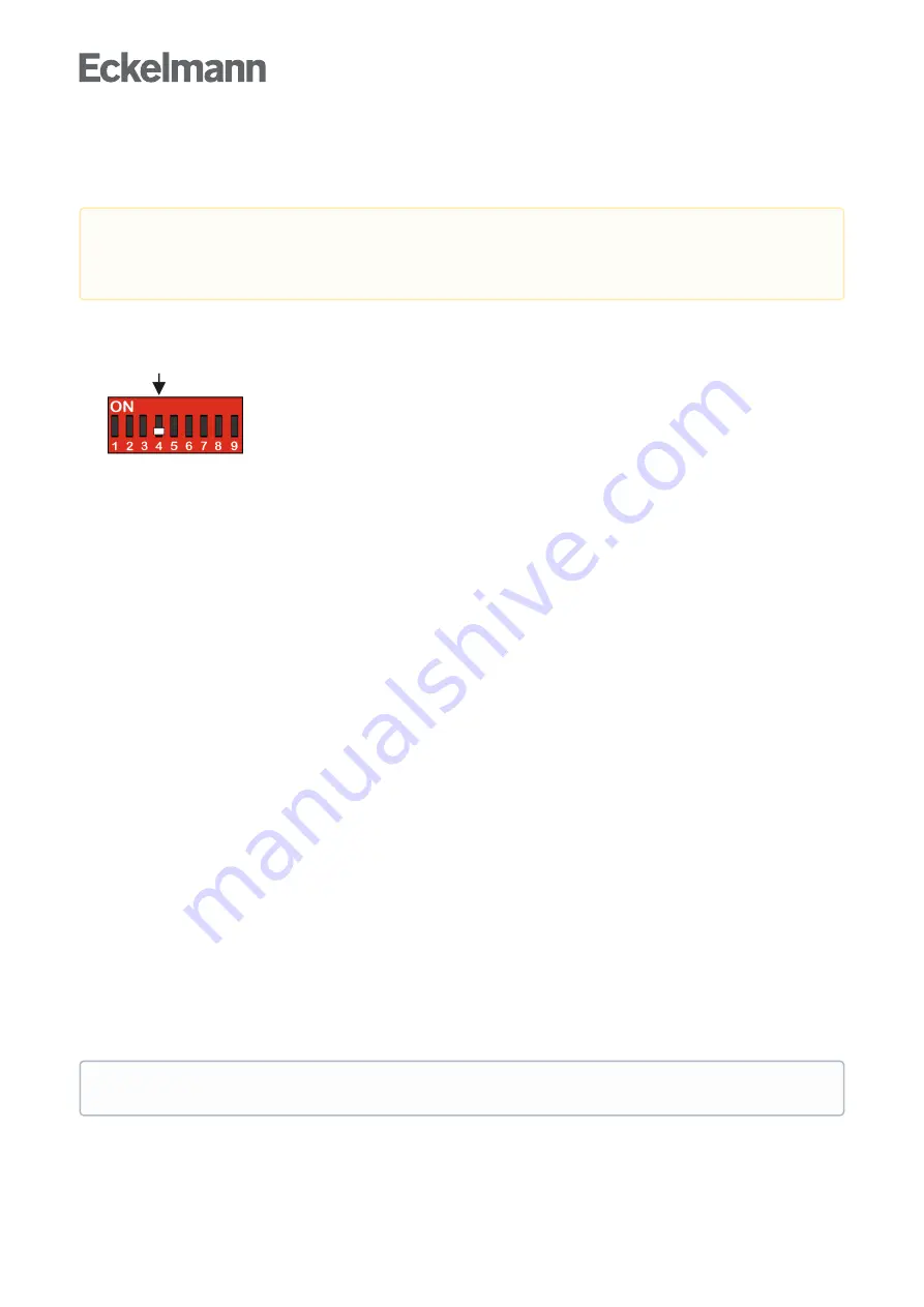
Requirements
Setting of the DIP switch S3, coding switch 4
must
be set to
OFF
controller type and master/slave mode
.
Software settings, see below for details.
Function Description
The master/slave mode is used for refrigerated cases, for which the operation of multiple evaporators can result
in reciprocal icing of the evaporators without further protective measures.
This problem is prevented due to the defrost synchronisation in master/slave mode. All refrigerated cases and
case zones defrost simultaneously and then switch to cooling together. For this type of master/slave mode,
multiple involved controllers are synchronised via the CAN bus.
The master/slave defrost covers the following function: Following a joint defrost, a group of controllers only
switches back to cooling when all the controllers have completed their respective defrost. Therefore, the
transition from defrost to cooling operation is synchronised for all the case controllers in a defrost group.
The case controllers in the defrost group are divided into one defrost master and the defrost slaves. The defrost
master sets the defrost start, and at the end of the process, enables cooling again. All the other defrost
participants (when existing) are called defrost slaves and follow the instructions of the defrost master. Several
independent defrost groups can be realised, i.e. a number of defrost masters who each administer an arbitrary
number of defrost slaves. In addition to the defrost groups, further controllers entering defrost within the system
can exist independently of the groups.
The size of the defrost groups as well as the number of defrost groups is only limited by the maximum number
of participants in the E*LDS system.
Execution or sequence of the master/slave defrost via the CAN bus
A defrost is initiated at the master. From this point in time, all the slaves enter a defrost. As long as any of the
participants (slaves or the master) is still in defrost, none of the controllers involved will switch to cooling.
f the defrost end temperature has been reached at one of the controllers, this controller sets its own defrost
relay to OFF, but remains in the defrost state and does not change to the cooling state.
When all controllers involved have reached the end of the defrost cycle (whether via the safety time or via the
defrost termination temperature), they all return to the "cooling" state together.
The safety time set at the master and any waiting or dripping time set at the master is also used by the slaves.
Configuration / parametrisation of master/slave defrost via CAN bus
The controllers must be configured so that defrosting can take place. In the case of the master, a defrost is
activated via the internal clock, the external contact or via manual defrost (CAN/local). The master, with respect
to the parameter “
M/S Abt Fkt
” must be set to
“Master”
(menus 2-2-1 and 2-2-2). The parameter “
M/S CAN Adr.
”
is of no relevance for the master.
Damage to the installation and stock loss!
When using this function, it must be ensured that
incorrect parametrisation
does not result in simultaneous defrost and cooling of the synchronised
refrigeration points.
It is recommended to set the parameter “
M/S CAN Adr.
” on the master to “—“.
Summary of Contents for UA 400
Page 26: ...Firmware V3 15 21 04 2021 26 401 Solenoid valve Relay for Solenoid Valve 1 ...
Page 172: ...Firmware V3 15 21 04 2021 172 401 Service Mode 6 7 2 SERVICE MOD ...
Page 244: ...Firmware V3 15 21 04 2021 244 401 ...
Page 361: ...Firmware V3 15 21 04 2021 361 401 FANS 2 Pos XXXXX Fan Delay Fan delay ...
Page 372: ...Firmware V3 15 21 04 2021 372 401 ...


