FP-5000
IL17569C
Page 8-7
Effective Date: 12/05
Effective Date: 12/05
For more information visit:
www.eatonelectrical.com
Page 8-7
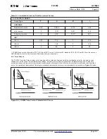
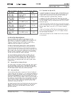
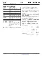
Table 8.2 Negative Sequence Current Protection Settings
Parameter
Range
Step
46-1 IUB
0.10 to 20 pu,
0.01 pu
Threshold
Disabled
46-1 IUB %
2% to 40%
1%
Unbalance
46-1 IUB
0 to 9999 Cycles
1 Cycle
Delay
46-2 IUB
0.10 to 20 pu,
0.01 pu
Threshold
Disabled
46-2 IUB %
2% to 40%
1%
Unbalance
46-2 IUB
0 to 9999 Cycles
1 Cycle
Delay
8.4 Curve Overlapping Issues
Several calculations are performed simultaneously for the
determination of trip and alarm conditions. Each of these trip and
alarm criteria are considered independently of each other.
Whichever condition occurs first will cause the fault with no
additional coordination between the processes.
8.5 Zone Interlocking Behavior and Application
To minimize damage to the system, faults should be cleared as
quickly as possible. Zone interlocking provides this capability better
than a system with only selective coordination. Zone interlocking
functions must be programmed (see Section 5.5.2.9) before they
can be used. By default the function is disabled.
The zone interlocking protection scheme provides a way for
a protective device to determine if a device, in a downstream
zone, picks up a fault and is taking action. With this information,
the protective device can immediately trip if no other device is
taking action or use its programmed time delay if another device
is taking action.
8.5.1 Compatible Zone Interlock Devices
The Cutler-Hammer FP-5000 and DT-3000 protective relays support
the zone interlocking function and are compatible with each other.
Refer to the DT-3000 instruction book (I.B. 17555) for details on the
DT-3000 implementation of the zone interlocking function.
8.5.2 Connection Rules
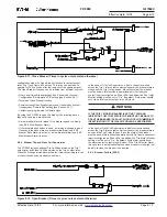
Zone interlocking information is passed on a two-wire Twisted pair
communication pair, see Section 6.11, for complete wiring details. All
devices in the same zone wire their zone-out terminals (J3-1 and J3-
2) in parallel see
Figure
8-10
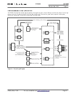
. Zone Interlocking Example with FP-
5000 and DT-3000. This daisy chained wire pair is then connected to
the upstream zone protection device zone-in terminal (J3-4 and J3-2).
Up to 10 devices can have their zone-out terminals wired in parallel.
Only one device, in the upstream zone should have these wires
connected to its zone-in terminals.
Any downstream device can drive the daisy chained wire pair active,
signaling that the device is going to take action. In this case the
upstream device will not trip immediately but will use the pro-
grammed time delay.
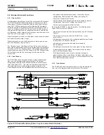
8.5.3 Operation (see Figure 8-10).
In general, if configured, the zone-out signal in a FP-5000 is driven
when the protective device is picked up on an Instantaneous Over
Current (IOC) or Inverse Time Over Current (TOC) in the same
direction as specified in zone interlock out direction.
In particular, if the Zone Out setpoint is “Phase” then any phase
directional permissive phase current IOC or TOC pickup will activate
the zone out signal. Ground or residual current IOC or TOC will not
activate the signal.
If the Zone Out setpoint is “Ground” then any directional permissive
ground or residual current IOC or TOC pickup will cause activation of
zone-out signal. Phase current IOC or TOC will not activate the
signal.
If the Zone Out setpoint is “Both” then any directional permissive
phase, ground and residual current IOC or TOC pickup will cause
the zone-out signal to activate.
If the Zone Out setpoint is set to “Disable” then the zone-out signal
will not activate.

