


IL17569C
Page 4-4
FP-5000
Effective Date: 12/05
Page 4-4
For more information visit:
www.eatonelectrical.com
Effective Date: 12/05
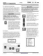
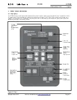
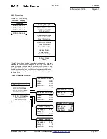
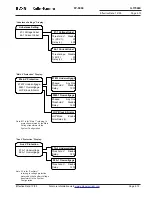
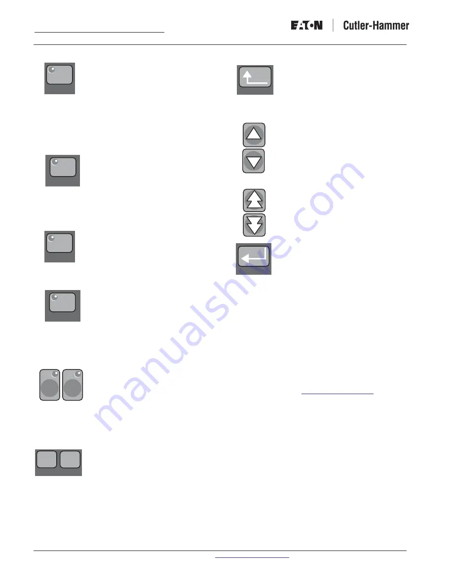
“Monitor” Pushbutton
The “
Monitor
” pushbutton allows the user to go
in to Monitor Mode and view all of the metered
values of the FP-5000: Load parameters,
Fundamental Phasors, Energy, Demand, and
Minimum & Maximum values. These values
include system power, currents & voltages,
frequency, power factors, THD, current & voltage
phasors, system demands, etc. Refer to Section
4.6 to see all parameters displayed while in
Monitor Mode.
“View Setting” Pushbutton
The “
View Setting
” pushbutton allows the user
to go in to View Settings Mode and view all of
the FP-5000 settings. It is important to note
when pressing the “View Setting” pushbutton,
the user can only go in and view the settings, not
change the settings. Refer to Section 4.6 to see
all settings displayed while in View Settings
Mode. Refer to Section 5 for programming the
settings.
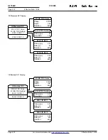
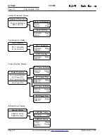
“Log” Pushbutton
The “
Log
” pushbutton allows the user to
go in to the Log Mode and view all of the data
recorded by the FP-5000. The Log data consists of
the Trip Log, Event Log and History Log. Refer
to Section 4.6 to see all data displayed while in
Log Mode.
“Status/Control” Pushbutton
The “
Status/Control
” pushbutton allows
the user to go in to the Status/Control Mode,
view all of the status parameters and set all of
the control parameters of the FP-5000. The user
can also view the Boot Code and Application
Code versions by selecting the “Version” sub-
menu. Refer to Section 4.6 to see all status and
control displays and options. Refer to Section 5
for programming the control options.
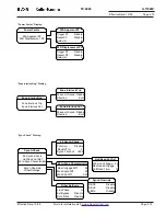
“Set” and “Test” Pushbuttons
The
“Set”
and
“Test”
pushbuttons are
accessed via the security door at the
bottom-left of the display panel. The
“Set”
pushbutton is used to enter the Setting Mode to
program the settings. The
“Test”
pushbutton is
used to enter the Test Mode which will run self-
tests and exercise the outputs. See Section 5
Settings and Section 11 Testing for detailed
information on setting and testing the FP-5000.
“Close” and “Open” Pushbuttons
The
“Open”
and
“Close”
pushbuttons
are used to initiate the breaker to
“open”
or
“close.”
Once either of these pushbuttons is
pressed, the user only has 10 seconds to
confirm the open or close breaker action. See
Section 8 for detailed information on breaker
control. These buttons must be activated via
settings to be operational. If disabled no
operation of the breaker will occur.
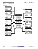
“Previous” Pushbutton
The “
Previous
” pushbutton allows the user to go
to the previous menu. Once the user is in a
“sub-menu,” the user can push the “previous”
pushbutton to revert back to the last display
screen. It is also used when the user is updating
settings to cancel out of saving the settings.
“Single and Double
Up/Down Arrow” Pushbuttons
Both of these pushbuttons allow the user to
scroll up and down the display menus.
The single arrow pushbuttons “
Up,”
and
“
Down,”
are used to scroll up and down the
menu structure display selections one line at a
time. They are also used to increment or
decrement setting values one step at a time.
The double arrow pushbutton
“Page Up,”
and
“
Page Down,”
scroll up and down the menu
structure in page increments rather than in
single line increments. They also increment or
decrement setting values 10 times as fast as the
Up and Down pushbuttons.
“Enter” Pushbutton
The “
Enter
” pushbutton allows the user to view
the display menus, which are chosen by the up/
down arrows. It also is used in the programming
mode to change setting values and save the
settings. Once a setting is chosen by the up/
down arrows, the “
Enter
” pushbutton is used to
enter that setting. If the
“Enter”
pushbutton is
not pushed when changing a setting, that setting
will not be changed.
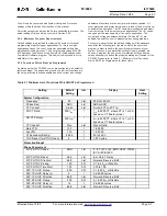
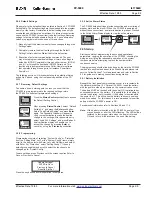
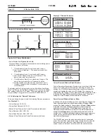
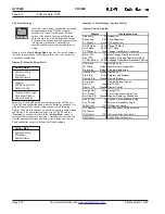
4.4 RS-232 Communications Port / Front Panel
Communication
The FP-5000 communications port (located on the bottom right of the
front panel) is a straight through DB9 RS-232 communications port.
It’s used to view the status of the FP-5000 and to download setpoints
via Cutler-Hammer’s Power Port Communications software and a
personal computer. It is also used for upgrading firmware using the
Flashloader program. PowerPort software can be obtained from the
Cutler-Hammer Internet site,
www.ch.cutler-hammer.com
.
The FP-5000 transmits communications on pin 2 and it receives
communications on pin 3, making it a Data Set or Data Communica-
tion Equipment (DSE/DCE) under the definitions of the RS-232
standard. The FP-5000 does not use the RS-232 hardware control
lines. Although the FP-5000 operates with the “3-wire” connection, a
standard off-the-shelf serial cable will allow communication. See
Figure 4-2
for the DB9 cable connections. An example of an off-the-
shelf cable is the RadioShack
®
, 26-117B, Male DB9 to Female DB9
Shielded RS-232C Cable.
See Section 10 for a detailed description of the FP-5000 communica-
tions and the Cutler-Hammer PowerPort software.
Monitor
View Setting
Log
Status/Control
Set
Test
Previous
Enter
Close
Open
Breaker