Effective Date: 12/05
For more information visit:
www.eatonelectrical.com
Page 5-39
FP-5000
IL17569C
Page 5-39
Effective Date: 12/05
5.4 Setting Descriptions
This section discusses the settings in a little more detail than the
settings table.
5.4.1 System Configuration Setting Descriptions
(System Config)
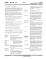
The System Config settings contain all of the settings to configure
the power system.
Frequency:
Nominal system operating frequency.
Phase Seq:
ABC or ACB system phase sequence or rotation.
CT Connect:
The “3-wire” setting should be used for three-
phase, three-wire, medium voltage power
systems. The “4CT In” setting should be used
on a three-phase, 4-wire system where a 4
th
CT is connected in the neutral conductor on.
The “4CT Ig” should be used on a three-phase,
4-wire system when a zero-sequence ground
CT is used. See Section 8 for more information.
PH CT Ratio:
The primary connected current rating of the
phase CTs. For example, set to 800 for phase
CTs of 800:5.
The FP-5000 is designed for use with current
transformers (CTs) having a nominal secondary
current of either 5 amperes or 1 ampere. The
FP-5000 CT Ratio setting is displayed as nnn:5
for a 5 ampere CT unit and nnn:1 for a 1 ampere
CT unit, where nnn is the primary rating of the
main CT. The setting range for the primary rating
is from 1 (5 for a 5 ampere CT) to 6000.
IX CT Ratio:
The primary connected current rating for the
fourth current input (usually for neutral or ground).
If the ground measurement is taken from a
residual phase connection then this setting will be
the same as the Phase CT Ratio setting above. If
a zero sequence or ground CT is used then the
primary rating for that CT will be used.
VT Connect:
Voltage transformer connection – wye or
“open” delta.
Main VTR:
Main voltage transformer ratio to one.
Example: 13.2 kV system, 120 V VT – set Main
VTR to 110 = (13200/120)
Aux VTR:
Auxiliary voltage transformer ratio.
See example above.
VT Secondary
Rating:
This set point is the voltage across the VT
secondary when nominal voltage is applied to
the primary.
Prim Units:
Selection of Primary units for metering voltage
and current displayed values.
If setting is “Yes”, then all voltages and currents
(including sequence voltages and currents) will
be displayed in primary values, which are
system values.
If setting is “No”, then all voltages and currents
(including sequence voltages and currents)
will be displayed in secondary values, which
are the actual values measured at
the FP-5000 inputs.
Power and energy readings are always in
primary values.
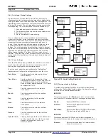
I/O Config:
The user may select either default input/output
configuration or customized input/output configura-
tion. The I/O refers to the contact inputs and output
relays. Choosing customized I/O allows the user
to freely program the contact inputs and relay
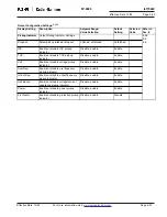
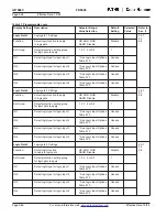
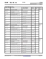
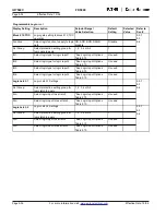
outputs. See Table 5.16 Contact Input CFG and
Output CFG settings and the following descrip-
tions for more information. The unit is shipped
from the factory with “I/O Config” set to default.
The I/O cannot be changed from the default
setting unless this setting has been set to Custom
I/O. A Default I/O setting will not give the user
access to the configured I/O settings in the Set
Mode. To view I/O configuration, the user will
need to exit the Set Mode and enter the View
Setting mode and scroll to the appropriate section.
If the relay I/O has been customized, then selecting
the “Default I/O” will change all the Custom I/O
settings back to the factor default settings.
Changing this setting will immediately ask you
to confirm and save the settings and will exit
you out of the setting mode. You will need to enter
back into the Set Mode to continue your pro-
gramming session. Please note that all settings
made prior to this point will be saved upon the
confirmation to save the settings. This update is
necessary for the relay to know if I/O configuration
is permitted and to give access to these settings.
Prog Logic:
The user may select either the default program-
mable logic or customized programmable logic
settings. Choosing customized programmable logic
allows the user to freely program all of the logic
gates. See “Programmable Logic” Table 5.7
settings and in the descriptions below for more
information. The unit is shipped from the factory
with “Prog Logic” set to default.
The programmable logic cannot be changed
from the default settings unless this setting has
been set to Custom Programmable Logic. A
Default programmable logic setting will not give
the user access to the Programmable Logic
settings in the Set Mode. To view programmable
logic configuration, the user will need to exit the
Set Mode and enter the View Setting mode and
scroll to the appropriate section. If the relay
programmable logic has been customized; then
selecting the “Default Programmable Logic” will
change all the Custom Programmable Logic
settings back to the factory default settings.
Changing this setting will immediately ask you
to confirm and save the settings and will exit you
out of the setting mode. Please note that all settings
made prior to this point will be saved upon the
confirmation to save the settings. This update is
necessary for the relay to know if Programmable
Logic configuration is permitted and to give
access to these settings.
Remote Set:
This setting Enables or Disables the remote
capability of downloading setpoints via the rear
communication port using Cutler-Hammer’s

