IL17569C
Page 5-46
FP-5000
Effective Date: 12/05
Page 5-46
For more information visit:
www.eatonelectrical.com
Effective Date: 12/05
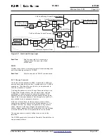
The Displacement Power Factor is computed by dividing the
fundamental watts by the fundamental volt-amperes as shown
below. This definition is only valid at the system fundamental
operating frequency. The Displacement Power Factor isolates
the fundamental portion of the Power Factor from the effects
of harmonics.
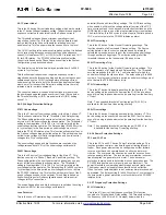
New values of apparent and displacement power factor are
computed every 32 cycles. The power factor function operates when
the power factor is more lagging than the Trigger PF setting for the
Power Factor Delay setting time. The function resets when the power
factor is more leading than the Reset PF setting for the Power Factor
Delay setting time.
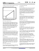
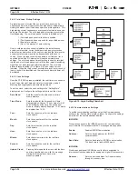
5.4.2.10 Zone Interlocking
Zone Interlocking
The zone interlocking setting consists of settings to configure a Zone
Interlock Trip and a Zone Interlock Out setting. Both Zone Interlock
Trip and Zone Interlock Out settings can be set to Disable, Phase,
Ground, or Both. Both Zone Interlock Trip and Zone Interlock Out
can be set to Forward, Reverse or Both.
set the level above maximum load
currents even though the Breaker
failure logic is only initiated upon a
breaker trip
The I Gnd (pu) is an independent
ground overcurrent element that
uses both the measured residual
ground current (Ir) and the measured
ground current (Ix). It is recom
mended to be set above any normal
or expected rms ground currents.
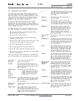
5.4.2.9 Power Factor
55A Apparent PF and 55D Displacement PF
These are the two Power Factor protection settings: 55A device is
the Apparent Power Factor setting and 55D device is the Displace-
ment Power Factor setting. There are three settings, which are the
same for the apparent and displacement power factor function:
Trigger PF:
This setting is the apparent power factor that the
FP-5000 will trip on.
Reset PF:
This setting is the apparent power factor at which
the FP-5000 will reset the apparent power factor
function. It is like setting a hysteresis for the
Trigger setting.
Delay:
This setting defines the delay (in seconds) that the
Trigger PF must be active before the FP-5000 will
initiate a trip signal.
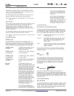
The Apparent Power Factor is computed by dividing real power
(watts) by volt-amperes. The apparent power factor computation
includes harmonics.
PF
apparent
=
50BF Bkr
Failure:
underfrequency function operates. The Delay setting (0 to 9999
cycles in 1-cycle steps) is the time period an underfrequency must
occur before the FP-5000 initiates a trip.
The underfrequency pickup and trip functions are reset when the
frequency raises above the underfrequency set threshold.
Note: Phase A voltage must be greater than 10 V for this function
to operate.
81O-1 Overfreq:
This is the 81O device Overfrequency setting. This function consists
of a Threshold and Delay setting. The Threshold setting is the
frequency (45-65 Hz in 0.01 Hz steps) above which the
overfrequency function operates. The Delay setting (0 to 9999
cycles) is the time period an overfrequency must occur before the
FP-5000 initiates a trip.
The overfrequency pickup and trip functions are reset when the
frequency drops below the overfrequency set threshold.
Note: Phase A voltage must be greater than 10 V for this function to
operate.
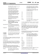
5.4.2.8 Breaker Failure
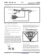
50BF Bkr Config
This is the 50BF device Breaker Failure Configuration setting. The
50BF Bkr Config sets the conditions for the FP-5000 to detect a
breaker failure condition. This function is only activated after initiation.
The four 50BF Bkr Config setting descriptions are shown below:
50BF Bkr Config
The 50BF device is turned off, so no
set to Off:
breaker failure can be detected
internally or externally.
50BF Bkr Config
The 50BF function will be initiated by
set to Internal:
an internal trip signal.
50BF Bkr Config
The 50BF function will be initiated by
set to External:
an external signal.
50BF Bkr Config
The 50BF function will be initiated by
set to Both:
either an internal or external trip
signal.
This includes the 50BF device
Breaker Failure setting, which is only
applied if the 50BF Bkr Config setting
is not set to “off.” The default con
figuration for the output logic maps
the Breaker Failure trip (i.e. Breaker
State Lockout) to output Relay 3 so
that a separate lockout relay (device
86) can be used to provide backup
tripping. The breaker failure function
continues to monitor all phase
currents after a trip is initiated by
either the FP-5000 or an external
device. The breaker failure trip output
operates if the phase or ground
currents do not drop below the
programmed I Ph (pu) or I Gnd (pu)
setting levels within the breaker
failure Delay time setting.
The I Ph (pu) is an independent
overcurrent element monitoring the
phase currents. It is recommended to
watt
VA
PF
displacement
=
watt
(watt
2
+ var
2
)


