Table of Contents
Section 1 Introduction
1.1
General
2
1.2
Receiving
2
Section 2 Installation
2.1
Location
3
2.2
Clearances
3
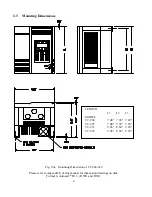
2.3
Mounting Dimensions
4
2.4
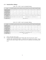
Standard drive ratings
8
2.5
Common specification
10
Section 3 Wiring
3.1
Interconnection
11
3.2
Hoist interconnection diagram
12
3.3
Wire size & circuit breaker selection
13
3.4
Grounding
14
3.5
Motor thermal overload relay
15
3.6
Brake motor magnetic contactor
15
3.7
Special cautions on wiring
15
Section 4 External connection layout
4.1
Component outline
17
4.2
Function description of main circuit terminal (TM1)
19
4.3
D61530 120V isolator instructions
23
4.4
Function description of control terminal (TM2)
26
Section 5 Digital operator control
5.1
Introduction and configuration
32
5.2
Function parameter setting
35
5.3
Function code descriptions (Fn00-Fn71)
36
5.4
Factory default load 'Quick Set'
57
Section 6 Test run
6.1
Precautionary checks before test running
59
6.2
Test run
60
Section 7 Setting and adjustment
7.1
General description of settings and adjustments
61
7.2
Example of digital operator control and frequency command
62
Section 8 Fault indications
64
Section 9 Maintenance
68
Reference
a. Measurement of voltage and current
69
b. Troubleshooting procedure.
70
c. Electromagnetic compatibility (EMC) of inverter.
72
Appendix A Peripheral - Ground Fault Protection
76
Appendix B Peripheral - Digital Operator Extension
77
Appendix C - User Program List
78
Appendix D - Terminal Function List
80
Appendix E - D61530 (D61531) Input Isolator Instructions
81
Appendix F - 'B' size working schematics
i

