23
4.3
D61530 120V 'DIRECT COMMAND' INPUT ISOLATOR
D61531 24VAC 'DIRECT COMMAND' INPUT ISOLATOR
4.3.1 FUNCTION
The D61530 120VAC (D61531 24VAC) input isolator is designed to mount directly on the control
terminal strip (TM2) of Crane Commander model inverters. The function of the D61530 (D61531) is
to allow direct connection to 120VAC (24VAC) control inputs while providing filtering and isolation
to the Crane Commander. Each of 6 input lines are optically isolated from the corresponding logic
level output. A S.P.D.T. relay is provided for output of either running mode, at constant speed, or up
to speed. A convenient pull apart terminal strip (TB1) is provided for 120VAC (24VAC) input signal
connections.
4.3.2 MOUNTING
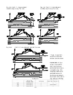
Refer to Figure 4.3 for description of mounting procedures. The D61530 (D61531) mounts directly
to the lower tier of the Crane Commanders control terminal strip (TM2). The terminal strip connec-
tions provide support for the printed circuit board and 6 connection points: COM, SP2, REV, SYN+,
+VE, -VE. The other 5 connections are made by way of flying wire leads: FWD, SP1, SP3, RST,
SYN-.
4.3.3 MOUNTING INSTRUCTIONS
DANGER! Hazardous voltage within can cause serious injury or death. Operating drive from
keypad may disable safety circuits and result in danger or injury. Only qualified personnel
should work on this equipment after familiarization with its operation. Turn OFF and lock out
power at main panel. Allow capacitors to bleed off prior to servicing
.
Insure all power sources are removed from Crane Commander and system and that D.C. bus is
discharged prior to handling Crane Commander inverter.
1)
Remove cover of Crane Commander inverter to expose main printed circuit board terminal
strip (TM2).
2)
Connect all wires to lower power terminal strip (TM1) first since this terminal strip will not be
accessible once the D61530 (D61531) is installed. Keep wire length as short as possible to
prevent interference with D61530 (D61531). Follow the Crane Commander connection
diagram for wiring connection.
3)
Remove screws COM, SP2, REV, SYN+, +VE, -VE on lower tier of terminal strip.
4)
Place D61530 (D61531) on to terminal strip (TM2) making sure to check that corresponding
terminals are aligned correctly. Replace 6 screws and tighten each starting from center and
working outwards. There will be a screw on each side of TM2
not
connected to the D61530
isolator. Tighten to 10 in-lbs.


