26
4.4 Function Description of Control Terminal (TM2) Located directly on control PCB of
Crane Commander and TB1 of D61530 120V (D61531 24VAC) isolator PCB which directly
connects to 120VAC inputs. (or 24VAC in case of D61531)
4.4.1 Terminals 1 and 2 of TM2
Function: Fault Relay. Used in all cases with or without D61530 (D61531) installed.
Terminal 1 & 2 of TM2 are N.O. (
Fn13=0
) or N.C. (
Fn13=1
) relay contact to output alarm signal
when protective circuit is activated.
Contact rating: 250 VAC/ 1 Amp or 30 VDC/ 1 Amp.
4.4.2 Terminals 3 and 8 of TM2 and terminals F and R of TB1 on D61530 (D61531).
Function: FWD/STOP, REV/STOP Operation (effective in remote control
Fn 10
= 1 only).
Direction input terminals control operating direction of inverter and connected motor. Each direc-
tion is interlocked electronically. Should both directions become energized the inverter will stop
according to the selected stopping method if running or remain at rest.
NOTE:
Maintained contacts are required for continuous operation under any operating conditions.
WARNING:
Should coast to stop (immediate brake on) be selected as the stopping method (default
for hoist quick set parameters) the following must be observed:
1) Mechanically interlock pushbuttons must be used for up and down.
2) The motor must come to rest before the other direction of operation is selected.
Failure to do this will result in inverter damage as a result of reverse plugging operation of motor.
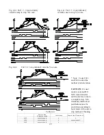
Fig. 4.4a 120VAC or 24VAC
circuit connection
Fig. 4.4b 24VDC circuit
connection
Fig. 4.4c Operation method
selection example. Decel to
stop selected.


